Do you have a question about the JYE Tech 13803K and is the answer not in the manual?
Basic tips for soldering components evenly and cleanly on PCB pads.
List of essential tools needed for the oscilloscope kit assembly.
Instructions for identifying and installing various resistor values.
Guide for installing the HF-chokes (inductors).
Instructions for identifying and installing diodes, noting polarity.
Guide for installing the 8MHz crystal oscillator.
Instructions for installing the USB mini-B socket.
Guide for installing the 6x6x5mm tactile switches.
Instructions for installing various ceramic capacitors.
Guide for installing the LED, noting polarity and color.
Instructions for installing the 2-pin header for power input.
Guide for identifying and installing transistors (8550, 9014).
Instructions for installing voltage regulators (79L05, 78L05).
Guide for installing capacitor trimmers (5-30pF).
Instructions for installing the power inductor (1mH).
Guide for installing electrolytic capacitors, noting polarity.
Instructions for installing the DC power connector.
Guide for installing male pin headers (e.g., 1x3, 1x4 pins).
Guide for installing female pin headers (e.g., 1x2, 2x20 pins).
Instructions for installing the 2P3T slide switches.
Guide for installing the BNC connector, noting thicker pins.
Instructions for creating a test signal ring and soldering JP3.
Steps for connecting the LCD board to the main board.
Procedure to check critical voltages after power connection.
Steps to verify the LCD board functions after connection.
Checking basic functions after assembly and initial power-up.
Instructions on connecting probes and initial scope usage.
Guidance for diagnosing and resolving display or power problems.
Explanation and usage of the oscilloscope's diagnostic test mode.
Reference voltage values for testing specific points on the board.
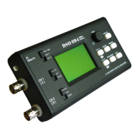
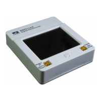
Overview of the oscilloscope's screen layout and physical controls.
Details on connecting the power supply and input probe.
Instructions for adjusting parameters like sensitivity and position.
Steps to calibrate the zero-volt line on the display.
Procedure to calibrate the probe for accurate high-frequency measurements.
How to enable or disable measurement readouts on the screen.
Instructions for storing and retrieving captured waveforms.
Detailed explanation of Auto, Normal, and Single trigger modes.
Key technical specifications of the DSO138 oscilloscope.
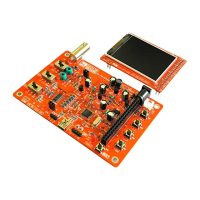
This document provides a comprehensive guide for assembling, testing, and using the DSO 138 Oscilloscope DIY Kit. It's designed for hobbyists and electronics enthusiasts who want to build their own oscilloscope. The manual is structured to walk users through each step, from soldering individual components to performing initial tests and understanding the device's operational features.
The DSO 138 Oscilloscope DIY Kit, once assembled, functions as a basic digital oscilloscope. Its primary purpose is to visualize electrical signals, allowing users to observe waveform shapes, measure voltage levels, and analyze signal frequencies. This device is particularly useful for educational purposes, basic circuit debugging, and hobby electronics projects where a full-featured, expensive oscilloscope might be overkill. It provides a visual representation of how voltage changes over time, which is fundamental for understanding and troubleshooting electronic circuits. The oscilloscope can display various types of signals, from simple DC voltages to more complex AC waveforms, and offers different trigger modes to stabilize the display of repetitive signals.
The usage of the DSO 138 oscilloscope involves several key features and controls:
The manual implicitly covers maintenance through its assembly and troubleshooting sections:
Overall, the manual provides a comprehensive framework for building, operating, and maintaining the DSO 138 Oscilloscope, making it accessible even for those with limited prior experience in electronics assembly.
| Category | Test Equipment |
|---|---|
| Model | 13803K |
| Brand | JYE Tech |
| Type | Oscilloscope |
| Channels | 2 |
| Input Impedance | 1 MΩ |
| Sampling Rate | 1 MS/s |
| Sensitivity | 10 mV/div to 5 V/div |
| Coupling | AC/DC |
| Display | 2.4" TFT LCD |
| Resolution | 320x240 pixels |
| Power Supply | DC 9V (8-10V acceptable) |