Iron(20W)
1
Solderwire
Multimeter
Screwdriver
AssemblyGuide
Rev.03
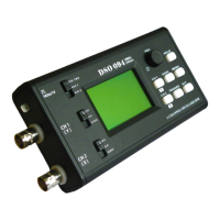
DSO068OscilloscopeDIYKit
2
3
4
Flushcutter
5
Tools
Checkpartvalues&quantitiesagainstpartlist
1
Meterandidentifyresistorvaluesbyohmmeter
Understandallpartpolaritiesandorientations
2
3
GetReady
Tweezers
6
Putleadsthroughmountingfrominstallationsideof
PCB.EnsuetheyevenlytouchPCB(picturebelow).
1
SolderattheothersideofPCB.Soldershouldfully
fillandcoversolderingpads.
Avoidbridgeswith
neighberingpads.
Cutunusedleads
flushwithcutter.
2
3
PartList
A. B. C. D. E. F.
BOBBoardInstallation
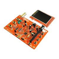
AssemblytheMainBoard
LED
Neg.P.S.
Conv.
Diode
ElectrolyticCap.
Resistor
Reset
USB-UartConv.
Inductor
USBSocket
Volt.Step-upConv.
Main
MCU
Transistor
CeramicCap.
CBBCap
Cap.Trimmer
Crystal
LCD
Contrast
Adj.
PowerSwitch
External
P.S.Conn.
Batt.Charger
BackSide
SlideSwitch
LCDModule
RotaryEncoder
FrontSide
Cutleadsshort
underLCD
A.
LayPCBflat.Insertmount-
ingstripswithlongerpins
intoholes.
Labels
B. C. D.
LCDInstallation
Step1
SolderingSkillsandRequirements
Payspecialattentiontopartpolarityatsoldering.Refertophotostotheright.
ForBOBboardsandLCDsolderingrefertophotosatbottomfordetails.
1.
2.
Installpartsbytheorderofpartlist.Startfromthebacksideofmainboard.
3.
Performpower-uptestsassuggestedinthepartlist.
4.
Completethestepsin"GetReady"andunderstandsolderingrequirements.
5.
Important!UnusedleadsunderLCDmustbecutflushtoavoidshorttoLCDmodule!
+
-
+
-
+
-
E
B
JYE116 JYE117 JYE118 JYE119 JYE120
Diode LED Electrolyticcap. Transistor
Identify
Polarity&
Orientation
()Pin1indicatedbyarrow
510K5%1/8WΩ,,
200KΩ,,1%1/8W
2MΩ,,1%1/8W
20KΩ,,
1
%1/8W
300Ω,,1%1/8W
180Ω,,1%1/8W
120,1%,1/8WΩ
3.3KΩ,,1%1/8W
470Ω,,1%1/8W
10K1Ω,,%1/8W
1K5Ω
,,%1/8W
2
2
1
1
1
3
1
2
3
3
5
R1,R27
R3
R2,R4
R5
R6
R7
R8,R12,R21
R10,R22
R11,R31,R33
R9,R20,R30
R24,R25,R26,R28,R29
300pF,ceramicdisk
3pF,ceramicdisk
1pF,ceramicdisk
120pF,ceramicdisk
0.1uF,ceramicdisk
100uF,16V,
φ
6
X7mm
10uF,16V,4φX5mm
15pF,ceramicdisk
1
12 C9,C10,C11,C12,C14,
C15,C16,C18,C20,C24,
C25,C26
2 C2,C23
C1
1
1
3
5
1
2
C17,C27,C28,C29,C30
C19
C21,C22
LED,3mmφ ,red D11
2
D2,D3
USBsocket,BtypeMiNi-
1 J1
2pins,2.54mm 1
J6
100uH,2.5X6mmφ 3 L1,L4,L5
8550,TO-92(E-B-C)
2
Q1,Q2
Tact,6X6X5mm
1 SW12
20MHz,φ2X6mm
1 Y1
0.1uF/100V,CBB
1N4148DO-35,
C4
C6
C7,C13,C32
JYE119,UART-USBconv.
JYE118,batterycharger
JYE117,On/Offswitch
JYE116,step-upconvertor
JYE120,neg.P.S.convertor
BOB1
()
optional
BOB2
()
optional
BOB3optional
()
BOB4
BOB5
DC005,2.1
φ mmcore J21
1
1
1
1
1
Type/Spec
QtySeq.
DIP2.54mm5X2,,
SIP,2mm,20X1
SIP,2mm,2X1
2
1
2
J4,J5Donotinstall
()
LCD
128X64graphic,12864-16 1
LCD1
SlideswitchSS-23D06,
RotaryEnc.,EC11,10mm
3
1
SW1,SW2,SW3
SW4
PCB#:109-06800-00H 1
Catagory
Top(1),bottom(1),stand(1)
switchcaps(3),dialcap(1)
1set
7-keysiliconebuttonpad
2-coreheader/wire,10cm
2.3*8mm,selftapping
BNCBNC-KY,
1
2
1
4
2
5
6
4
7
9
8
10
11
12
13
14
15
16
3
28
26
22
23
24
25
33
32
27
29
17
20
30
18
31
21
19
34
39
38
37
35
36
45
42
43
44
40
41
46
47
1
BOBsandJumpers
()
BOB4
()
BOB3
()
BOB2
()
BOB1
()
BOB5
Battery
Conn.
Extention
Ports
Buzzer
A/DConverter
KeepJP1openifBOB2
isinstalled.Otherwise
closeit.
TIP: Resistorvaluesareeasilymis-read.
Metercheckingisstronglysuggested.
BOBBoardsOrientation
48
1
Shieldingwire,8cm
5V,passive,9X5.5mmφ 1 BP1
49
Note:PleaseinstallbytheordergiveninthePartListbelow.
TIP: C3andR32
arenotrequired.
TIP: DonotinstallJ4ifbatteryistobemountedonbackcover.Insert
thepinsintoprogrammerheadertoperformU4andU5programming.
KeepJP2openifBOB3
isinstalled.Otherwise
closeit.
Identifytheholeswithlabels
onLCD.Theyshouldgo
withthelongstrip.
PutLCDontostripsasshown.
Solderpinsatcornersfirst.Do
therestafterflatnessensured.
TurnLCDandmainboardover.
Completesolderingfollowing
sameproceduresasinC.
Usethesmallacrylic
toolprovided.
Applysoldertoone
pin.
Applysoldertothe
correspondingpinon
mainPCB.
PutBOBtoplace
andalignpads.
MaintainBOBupright
andfixitbymelting
thesolder.
Finishtherestpins.
Designator/Location
MainPCB
Resistor
Diode
Inductor
Crystal
Connector
Switch
Capacitor
Buzzer
Diode
Transistor
Connector
Electro.
Capacitor
Connector
BOB
Board
Performpower-uptest1asdescribedonthereversepage.
Switch
Switch
Pin
Strip
Pinstrip
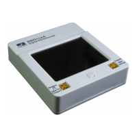
Enclosure
Switch
Wire
Wire
Connector
Screw
- www.jyetech.com -
JYETechLtd.
Moreatthereversepage
1
10M,5Ω
%,1/8W R40
50
Continuefollowingassemblyafterthetest.
Keypad
MCU
Test
Signal
Output
Pin1(squarepad)indicated
byarrow
1
Shortwithsolder JP9
Jumper
Performpower-up
test2asdescribedon
thereversepageafter
allcomponentshave
beeninstalledon
board.
()
PCBVersion:H