Iron (20W)
1
Solder wire
Multimeter
Screw driver
User Manual
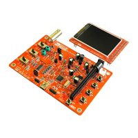
DSO 138 Oscilloscope DIY Kit
2
3
4
Flush cutter
5
Tools you need
Tweezers
6
- www.jyetech.com -
JYE Tech Ltd.
1. Resistors
Always meter resist or
values before soldering
Note:
R1, R14, R16
100K
R2
1.8M
:
:
R3
200K
:
R4
2M
:
R5
20K
:
R6
300
:
R7, R36
180
R8, R12, R13
120
:
:
R9, R15, R26
1K
:
R10
3K
:
R38
1.5K
:
R28, R40
470
:
R37, R39
10K
:
L1,L3,L4
100 H
2. HF-Chokes
:
D1
1N5819
3. Diodes
:
D2
1N4004
:
(or 1N4007)
Y1
8MHz
4. Crystal
:
J4
USB mini -B
5. USB Socket *
:
6 X 6 X 5 mm
6. Tact S witches
:
SW4, SW5,
SW6, SW7,
SW8
7. Ceramic Capacitors
0.1 F
:
330pF
:
3pF
:
C1, C 9,
C10, C11,
C14, C15,
C16, C17,
C18, C20,
C23
1pF
:
C7, C8
12 0p F
:
C12, C13
22pF
:
C2
C3
C5
D3
8. LED
:
3mm, green
Solder positive pole
(the longe r lead) to
the s quare pad
J9
2 Pin
9. Pin header (for power)
:
Face the opening
outward
855 0
10. Transistors
:
Q1
901 4
:
Q2
Cathode
79L05
11. Regulators
:
U4
78L05
:
U5
C4, C6
5 - 30pF
12. Capacito r trimmers
:
L2
1mH/0.5A
13. Power inductor
:
14. Electrolytic capacitors
:
100 / 16 V
F
So lder positive pole
(the longer lead) to
the square p ad
C19, C21,
C22, C24,
C25, C26
DC005
15. Power connector
:
J10
16. Pin-header (male) *
1 X 3 pin
:
J5
1 X 4 pin
:
J6
17. Pin-header (female)
:
1 X 2 pin
J7, J8
:
2 X 20 pin
J3
SW1, SW2 ,
SW3
2P3T
18. Slide switches
:
J1
BNC
19. B NC con nector
:
Put leads through mounting holes from the side with
part outline. Ensue component evenly touch PCB.
1
Sol der leads at the other side. Solder should fully
fill and cover so ldering pads.
Avoid bridges between
neighbering pads.
Cut unused leads
flush with cutter.
2
3
Soldering Hints
Check part values & quan tities against part list
1
Always meter resistor values before soldering
Un derstan d all part polarities and orientations
2
3
Before you start
Page 1
Packag es are simi lar.
Do not mix up!
Packages are similar.
Do not mix up!
The thicker pins need
to heat up longer to get
good soldering result.
Note:
R11
150
:
These pin-headers are
optional.
Note:
Install all SMD parts before proceeding
to Step1 if you purchased kit 13804K.
This connector is
optional.
Note: