1
C. Verify
Co nnect power supply again. You should see LCD
lights up and oscillo scope panel displayed.
2
Press various buttons and mov e switches to v erify
their functions.
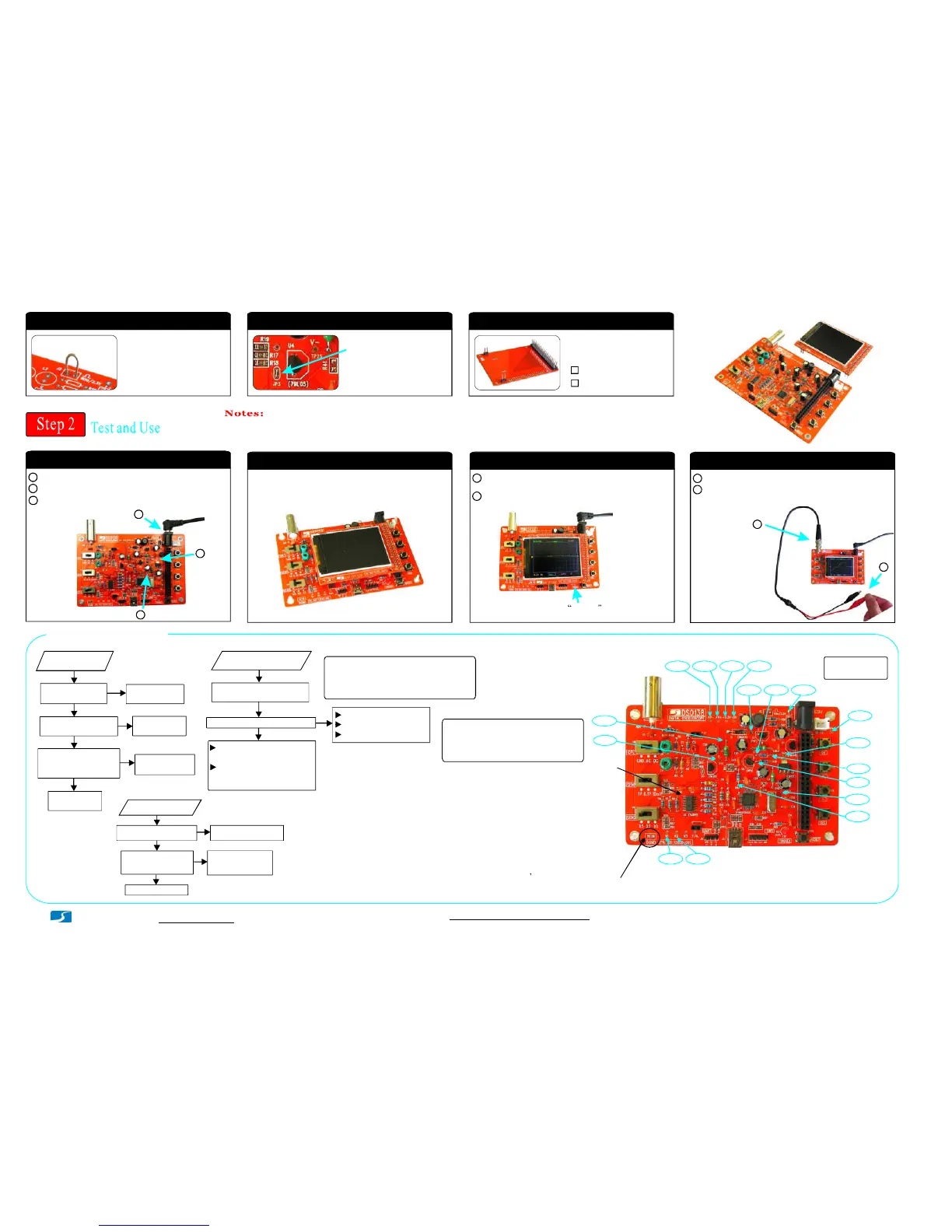
1 ) M ake a small r ing with a
lead cut-o ff.
20. Test signal ring
2 X 20 pin
22. LC D Board
:
J1
1 X 2 pin
:
J2, J3
2 ) S older the ring to the two
holes of J2 (as show n in
the photo).
21. JP3
Short JP3 with solder
Note: Install to the side
opposite to LCD panel.
3 ) A 9V DC power supply (> 200mA capacity) is required to run the scope. Power supply is not included in the ki t.
1
A. Check voltages
2
3
Apply 9V pow er to J10 (or J9).
2 Check voltage at TP 22. It sh ould be around +3.3V.
3
If voltage at TP22 is good disconne ct power. S hort JP4
with solder .permanently
1
B. Attach LCD board
Plug LCD board into the female headers J3, J7, and J8
on th e ma in board.
1
A. U se
Attach probe c lips to J1.
2 Touch the red clip with your finger. Do you see signal
from your finger?
1
- www.jyetech.com -
JYE Tech Ltd.
Troubleshooting
Is voltage at V+
good?
Check power
supply
Is R36 value correct
and soldered good?
Do you ge t about 3V
between J1 pin 16 &
18 on LCD board?
Fix R36
LCD Dark
No
No
Yes
Yes
(No backlight)
No
Yes
Check R36 and
power again
Check LCD
board
Press SW8. Does LED blink?
Check Y1, C12, C13
Check LED installation
Check +3.3V voltage
Check J3 soldering fo r
possible opens or shorts
No Display
Yes
No
Check J1 soldering on LCD
board for possible opens
or shorts (use Test Mode)
2
8.60V
9.39V
8.34V
3.3V
-1.39 V
2.16 V
0.81V
6.43 V0.19 V
5.02 V
3.3V
4.99 V
-5.0V
-8.08 V
-8.11V
1.66 V0V
*
*
**
*
*
*
**
**
Voltage
Reference s
(Input Volt age)
*: These v olt ages ar e inpu t voltage d epende n t. Th e v alues
sho w n w ere measured when inpu t voltage w as 9.3 9V.
**: These voltage s are mea sure d w hen CPL sw itch (SW1)
is set t o G ND pos ition.
NOT ES:
Place the negative pen of volt-meter
here to do volta ge measur e men ts.
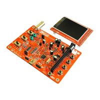
Finished look
Short JP4 if it has not been
done. See Step 2 above.
Check U2B, U2 C and
related parts around
these two a mplifiers
No
Se t CPL swit ch to GND
and me asure V1 and V2.
Are they correc t?
Chec k R1 2 and C8
Visit forum for detailed
troubleshooting guide
Are the values of AV+ and
AV- co rrec t?
No Trace
Yes
No
Yes
The volt ages in the pho to are for referenc e only.
The volt ages on your board could be diffe rent.
But the y should be clo se to the values show n.
NOTE 1:
www.jyetech.com/forum
Tech Support:
Trigge r LED blinking twice
indicates booting-u p is good.
Page 2
Test Mode
What it is and how it works
Test Mode is used to find out pos sible opens (for all port pins) and shorts
(for pins PB0 - 15 and PC1 3-15). When entered it first checks PB and PC
pins with special pattern s to find out possible shorts. If found LED will be
fast blinki ng. Otherwise, it generate 3.3V and 0V alternatively at each port
pins (PA, PB, PC and PD) in cycle of about 4 seconds. These signals can be
used to check for opens.
How to use
Hold do wn SW4 and press RESET to enter Test Mode.
If you see LED fast bli nki ng that means there are shorts on PB or PC pins.
You need to find out the shorts first.
If you see LED slowly blinking use a volt-meter to check each pi n related
connections that are suspected open. When you don t see voltage change
at a spot which is suppos ed being co nnected to a port pin there may be
open between the spot and the port p in.
1.
2.
3.
PIN 1
Mak e sure U1 and LED working
(y ou see LED blin ks twice at pressing
RESET) b efore using Test Mode.
NOTE 3:
LED will be blinking constantly if MCU
(U1) can not detect vali d LCD controller.
Check LCD pin-heade r soldering.
NOTE 2:
1 ) JP1, JP2, JP5, and JP6 at bottom side sh o uld be kept open for norm al running mode.
2 ) The US B conn e cto r do not have function. It was provided for future or user own use.
 Loading...