HOL D RUN/
Connec tors
for Power S upp ly
Trig ger Level
Rea d out
Horizontal
Positio n
Osc i ll osco p e
Mode
Connec tor
for Probe
Couple
Se l ection
Se nsiti vity
Se l ect ion 1
Sen s iti vity
Sel ection 2
Vertic al
Position
Indicator
Se nsitivi ty
Couple
Timeba se
Trigge r
Mod e
Trig ger
Slop e
Trig ged
Indicator
Trig ger
Leve l
Indicator
Parameter
Se l ection
Para m eter
Adjustment
Res et
Butt on
[+] or [-]:
[SEL]:
[OK]:
[CP L]:
[SEN1] :
[SEN 2]:
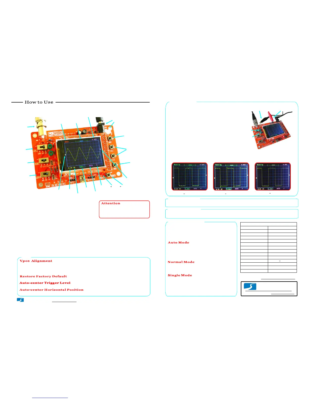
Display and Controls
Connections
Power Supply:
Co nnect DC power supply to J9 or J10. The power
supply voltage must be i n the range of 8 - 12V.
Probe:
Connect probe to J1.
Power supply voltage must not exc eed
12V. Otherwi se U5 will get hot.
1.
Allowed maximum signal in put voltage
is 50Vpk (100Vpp) with the clip pro b e.
2.
Operations
Press on [SEL] button:
Select parameter to be adjusted. The sel ected parameter will be highlighted.
Press on [+] or [-] button:
Adjust the parameter selected by [SEL] button.
Press on [OK] button:
Freeze waveform refresh (entering HOLD state). Press on it again will de-freeze.
Change [CPL] switch:
Set couple to DC, AC, or GND. When GND is selected the scope input is isolated from input
signal and connected to ground (0V input).
Change [SEN1] or [SEN2] switch:
Adjust sensi tiv ity. The product of [SEN1] and [SEN2] settings makes the
actual sensitivity which is displayed at the lower-left corner of the panel.
Press on [Reset] button:
Perform a system reset and re-boots the oscills cope.
Tips
This is to fix the mismatch between 0V trace and VPos i ndicator. To do this set couple s witch [CPL] to GND position.
Press on [SEL] button to make VPos indicator highlighed. Hold down [OK] button for about 2 seconds. You will see
VPos indicator aligned to 0V trace when you release [OK] button. You may see some residue mismatch remains at
the highes t sensitivity settings. This is normal.
Probe Calibratio n
Because there is alwa ys some capacitance between scope input and
ground probe needs to be calibrated to achieve better measurement
results for high frequency signals. This can be done with the help of
the built-in test signal. To do this please fol low the steps below.
Connect red clip to
test s ign a l output
Leave blac k clip
un- con nected
Connect the red clip to the te st signal terminal an d leave the
black clip un-connected (see pho to at right).
1.
Set [S EN1] swi tch to 0.1 V and [SEN2] switch to X5.
Set [C PL] switch to AC or DC .
2.
Adjust timebase to 0.2 m s. You s h ould see waveform similar
to that shown in photos below. If t races are no t st able adjus t
trigger lev el (the pink triangle on righ t screen bord er) so as
you get a stable display.
3.
Turn C4 (capacit or trimmer) with a small screw driver so that
th e waveform displays sharp rightangle (photo C ).
4.
C4
C6
Set [SEN1] switch to 1V and [SEN2] switch to X1while keep all ot her
settin g s unchanged. Ad just C6 so that sharp righta ngle waveform is
di splayed.
5.
A Not enoug h B Too much
C Good
Analog bandwidth
Se nsi tivity range
Resolution
Record length
Max realtime sample rate
Timebase range
Max input voltage
Input impedance
Power supply
Current consumptio n
Dimension
Weight
1MSa/s
0 -- 200KHz
10mV/div - 5V/div
50Vpk (1X probe)
1M ohm/20pF
12 bits
1024 points
500s/Di v -- 10us/Div
9V DC (8 12V)
~120mA
117 x 76 x 15mm
70 gram ( without probe)
Trigger modes
Trigger position range
Auto, Normal, and Single
50%
Specifications
Waveform S ave/Recall
Press [SEL] & [+] simultaneously: Save currently displayed waveform to non-volatile mem ory.
www.jyetec h.com
JYE Tech Ltd.
Tel. +86-0773-2113 856
Triggers and Their Modes
Triggers are even ts that indicate signal volt age acro ssing
a set lev el (i.e. trigger le vel) along a specified direction
(i.e. trigger slop e, rising or falling). Oscilloscope uses
triggers as reference poin ts in time for stab le waveform
dis play and measurements.
In aut o mode os cill oscope will perform display refresh no
matt er triggers happen or not. When triggers are detected
waveform display will be displayed with reference to
trigger points. Otherwis e, disp lay waveform at ramdom
reference points.
In normal mode oscilloscope will onl y perform dis play
refresh whe n there are t riggers. If no triggers happen
waveform display will stay unchanged.
Single mode is the same as no rmal mode ex cept that
oscillo scope wil l ent er HOLD state after a trigger has be en
detected and waveform display has bee n updated.
Normal and single modes are us eful for capturing sparse
or single waveform.
Se l ection
(s/div)
(V/d iv )
Tech Support: www.jyetech.com/forum
Page 3
- www.jyetech.com -
JYE Tech Ltd.
Turn On/Off Readouts
Press [SEL] so that timebase is highlighted. Hold d o wn [OK] button for about 2 seconds . This wi ll turn
on/off measurement readouts.
Press [SEL] & [-] simu ltane ously: Recall saved waveform
Hold down [+] and [-] buttons simultaneousl y for 2 seconds.
Highl ight trigger level indicator and hold down [O K] button for 2 seconds.Highl ight trigger level indicator and hold down [O K] button for 2 seconds.
Highl ight HPos indicator and ho ld down [OK] button for 2 seconds.
 Loading...