Do you have a question about the JYE Tech DSO 094 and is the answer not in the manual?
Details the function of various buttons like Power, RUN/HOLD, MENU, and knob adjustments for sensitivity, position, and time base.
Explains Y/T and Y/X modes for signal display and how to use the MENU button for special functions and mode switching.
Instructions for powering the device on and off, including initial battery connection for first-time use.
Guides on adjusting key parameters like sensitivity, position, time base, and trigger settings using control knobs.
Lists and explains special functions such as freezing waveforms, adjusting backlight, and fast adjustment modes.
Describes the Rolling Display Mode activated at slower time base settings for observing slow signals.
References a technical note for calibrating the 10X probe, directing users to an external resource.
Instructions for installing the PC driver and connecting the oscilloscope to a computer via USB.
Details on saving, recalling waveforms, and sending screen captures as bitmap files to a PC.
Guides on changing trigger position (pre-trig length) and adjusting trigger sensitivity for signal capture.
Instructions for changing record length, restoring factory default settings, and rebooting the device.
Explains how to set the oscilloscope to display one or two channels using the configuration switch.
Describes the integrated square wave test signal with its frequency and amplitude.
Information on battery life, the built-in charger, and charging via USB.
Details on how to upgrade the device firmware using the built-in bootloader.
Presents a detailed table of the oscilloscope's technical specifications and default parameters.
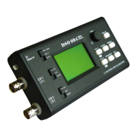
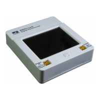
The DSO 094 is a two-channel oscilloscope designed for various signal analysis tasks. It features a compact and portable design, making it suitable for both benchtop and field use.
The DSO 094 operates primarily in two modes: Y/T Mode and Y/X Mode. Y/T Mode is the standard oscilloscope display, showing the relationship between a signal and time. This is the most commonly used mode for observing waveform characteristics over time. Y/X Mode, on the other hand, is used to graph the relationship between two signals, where Channel 1 represents the Y-axis and Channel 2 represents the X-axis. This mode is particularly useful for analyzing phase relationships or creating Lissajous figures.
The device includes a built-in test signal, which is a 1KHz square wave with an amplitude of approximately 1V peak-to-peak. This signal can be used for quick testing and calibration purposes.
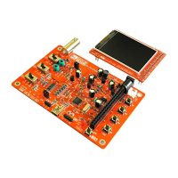
Powering On/Off: The device is powered on by pressing the [ADJ] knob and turned off by holding the [ADJ] knob for 2-3 seconds. For first-time use, especially after transportation, the internal battery needs to be connected by unscrewing the back cover and plugging the battery connector into the "BATT" header on the PCB.
Parameter Adjustment: Parameters are grouped into four categories: Channel 1 Vertical, Channel 2 Vertical, Horizontal, and Trigger. Each category has a dedicated button ([CH 1], [CH 2], [S/DIV], [TRIGGER]) to select parameters. Once a parameter is selected (indicated by highlighting), the [ADJ] knob is used to change its value.
Menu Navigation: The [MENU] button is used to access special functions and switch between modes. Pressing [MENU] enters the menu, and then [HOLD] is used to execute the selected item. Pressing [MENU] again exits the menu.
Special Functions:
Waveform Management: The device allows users to save captured waveforms to EEPROM and recall them later. The "SAVE WAVEFORM" and "RECALL WAVEFORM" functions are accessed via the menu.
Screen Sending: The "SEND SCREEN" function, also found in the menu, allows the device to send the current screen display as a bitmap file to a PC via a USB connection. This requires a PC application capable of handling XModem Protocol, configured for 38400bps, 8 data bits, 1 stop bit, no parity, and no flow control.
Record Length and Trigger Position: Users can change the record length (waveform buffer size) and trigger position (pre-trigger buffer size) through the menu. Trigger position is expressed as a percentage of the buffer size.
Trigger Sensitivity: The minimum level required to produce triggers can be adjusted via the "CHANGE TRIG SEN" menu option. It is expressed as a number of one-tenth of a major screen division size, with an adjustable range of 2-40.
Rolling Display Mode: When the timebase is set to 0.1s/Div or slower, the DSO 094 enters Rolling Display Mode, where traces shift from right to left across the screen to display slow signals continuously.
Input Voltage Warning: The maximum allowed input voltages are 50Vpk for a 1X probe and 400Vpk for a 10X probe. Users are explicitly warned against attempting to measure live line voltage directly with the device.
Battery Charging: The DSO 094 includes a built-in charger for its 3.7V 1200mAh Li-ion battery. Charging occurs at approximately 100mA and takes about 16 hours for a fully discharged battery. To charge, connect the USB port to a PC or a power adapter with a USB connector. A blinking battery sign indicates that charging is in progress.
USB Connection: For PC connectivity, the CP2102 driver needs to be installed. Drivers are available from the manufacturer's website. Good quality USB cables are recommended to prevent voltage drops that could affect device operation.
Firmware Upgrade: The device supports firmware upgrades for new functions or improved performance. This is done via the built-in bootloader. The "REBOOT" function in the menu provides a quick way to enter the bootloader.
Factory Default Settings: The "RESTORE DEFAULT" function in the menu allows users to revert all settings to their factory default values.
10X Probe Calibration: For details on how to calibrate a 10X probe, users are directed to a specific technical note available on the manufacturer's website.
| Channels | 1 |
|---|---|
| Vertical Sensitivity | 10 mV/div to 5 V/div |
| Input Impedance | 1 MΩ |
| Vertical Resolution | 8 bits |
| Coupling | AC / DC |
| Resolution | 8 bits |
| Interface | USB |
| Timebase | 1us/Div - 10s/Div |