Doublechecktoensurenomissedorcoldsolderorshorts
CloseJP2forthetimebeing(evenBOB3isinstalled)
KeepJP3JP4open、
CloseJP1ifnoBOB2
KeepJP1open
MakesureBOB2in
Powerup.Checkvoltage
at+5Vtestpoint.Isit+5V?
Poweroff.CloseJP4
Powerupandcheck+5V
again.Isitstill+5V?
LCDbacklighton ?
Adjustcontrast.Canyou
seedisplay?
Pressbuttons.Doyousee
reactiononscreen?
Setcursortotimebase.Turn
[ADJ]dial.Doyousee
timebasechange?
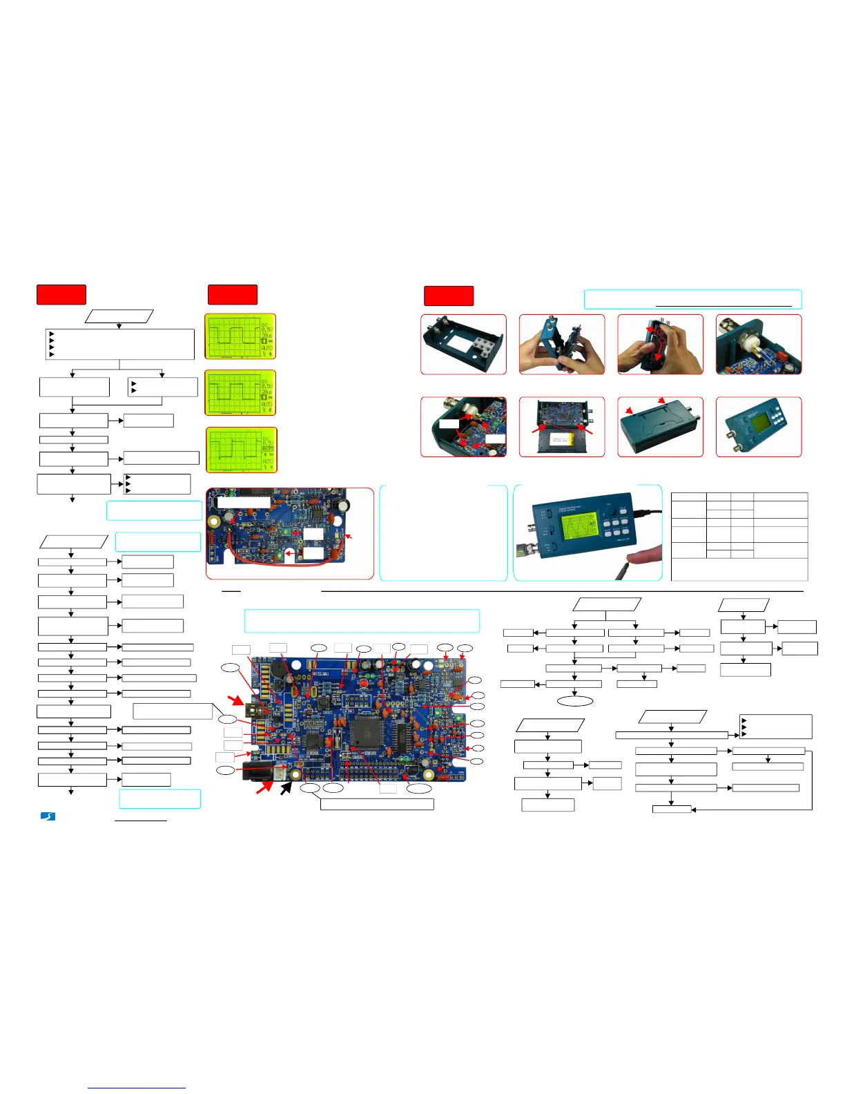
Powering-upTest1
Yes
No
USBpowered Batterypowered
MakesureBOB4andBOB5havebeeninstalled
Follow"NoPower"
flowcharttocheck
Checkforsolderingmistakes.
Wrongpolarity,shorts,etc.
Follow"LCDDark"
flowcharttocheck
CheckU5andsoldering
ofbuttonrelatedpins
Follow"Nodisplay"
flowcharttocheck
CheckU5andsoldering
ofrotaryencoderpins
V4
V1
V2
V3
AV-
AV+
V-
+5V
VT
VB
SYSCLK
VA
Contrast
Adj.
JP4
JP3
JP1
JP2
JP6
USB
Connector
(About+5V)
SignalInput
Referencepointfor
voltagemeasurement
*
Allvoltagesaremeasuredwithvoltmeter's(-)poleatreferencepoint(indicated
inphotobelow)and(+)poleatpointsofmeasurement.
1.
2.
*
Notes:
VBUS
V+
(Volt.range:2-5V)
Battery
Connector
VS+
WithoutBOB3VS+=V+(duetoJP2closed):
WithBOB3VS+dependsonstateofBOB3(OnorOff):
LCDpin18
IsV-normal(-5V)?
CheckBOB5andC27
CheckL1,C28,C11,andC12
CheckL5,C16,andC17
SetSW1,SW2,SW3toGND,
10mV,andX1respectively
IsVAnormal(+5V)?
CheckL4,C29,C9,andC10
IsV2measured0V? CheckSW1,SW2,andR1
IsV3measured0V?
U1mayhavebeendamaged
isV4measured~1.6V?
CheckSW3,R9,R10,R11
AdjustVPOS.Canyousee
tracedisplayed?
Follow"NoTrace"
flowcharttocheck
2
1
InstallBatter&
Enclosure
USBpowered Batterypowered
Batteryvoltageok?IsVBUSmeasuredok?
IsV+measuredok?IsV+measuredok ?
IsVS+measuredok?
Is+5Vmeasuredok?
BOB3installed?
Powergood
CheckBOB3
CheckJP2
Checkbatt.
CheckBOB2
CheckUSB
CheckD4
CheckBOB4
IsvoltageatLCD
pin195V?
Checkrelated
connections
ShortCandEofQ2.
DoesLCDlightup?
CheckQ2,R30and
connectionwithU5
PossibleLCD
issue
PressSW12.DoesLEDblinkasitshouldbe?
U4andLCDconnectiongood?
LCDdefective
Fixbadconnections
CheckY1,C21,C22
Re-programU4
VoltatU4pin20toolow?
IscontrastchangeablebyPOT1? VEE.atLCDpin18negative?
CheckPOT1andrelatedCheckallconnectionsbetween
U4andLCDforopensorshorts.
VTandVBnormal? U3damaged
ConnectionbetweenU4
pin17andU3pin12good?
U3hasbadsoldering
orhasbeendamaged
Checkout
thecause
Ensureallanalogvoltages
arenormal(seephoto)
PowerUpTests
Troubleshooting
A. B. C. D.
E. F. G. H.
PressSW12.DoyouseeLED
blinkonce(ifbootloader
installed)andthentwice?
CheckY1C21C22、、
LEDreversed?
U4pin20voltagelow?
Continuetoinstall
partsonthefront
PoweredbyUSB:V+VBUS-0.7V≈
PoweredbyBatt.:V+VBAT≈
()+5V
()-5V
()+5V
()-5V
()0V
*
()0V
*
()~1.6V
()0.6V
()2.6V
*
()0V
()+5V
()About-5V
(Batteryvoltage)
VBAT
()2.5V
V5
()~1.6V
www.jyetech.com/forum
JP5
AdjustCompensation
Capacitors
Compensationcapacitorscanbe
adjustedusingthebuilt-insignal
generator.Followstepsbelow:
C5
C8
Temporarilyconnecttestsignaloutputto
scopeinputwithapieceofwire
Notenough
通电检查
Good
通电检查
Toomuch
通电检查
1.
Connecttestsignaloutputtoscopeinput
(seephotobelow)andsetSW1toDC.
2.
Powerup.Settestsignalto10KHzand
5V.Setscopetimebaseto20us.
SetSW&SW3to1V&X2respectively.
Adjusttriggerleveltomakedisplay
stableifnecessary.ChangeC8toobtain
waveformasthemiddleofphotosleft.
3.
Keepsignalfrequenceunchangedand
setamplitudeto1V.SetSW2&SW3to
0.1VandX5respectively.Makedisplay
stable.ChangeC5toobtainwaveform
asthemiddleofphotosleft.
4.
5.
Removeconnectionbetweentestsignal
outputandscopeinput.Adjustmentis
done.
JP7 JP8
- www.jyetech.com-
Thisisby-passofchargerBOB2.Ifbattery
isnotused(i.e.noBOB2)keepJP1closed.
Thisisby-passofswitchBOB3.IfBOB3
isnotusedJP2shouldbeclosed.Inordertofocus
onthemaincircuitJP2canbetemporarilyclosed
atpower-uptestevenBOB3isinstalled.Keepit
openafterthetest.
JP2:
Thisisby-passofstep-upconverterBOB4.
UsuallyJP3shouldbekeptopen.
JP3:
Thisistheconnectingpointofpowersupply
totherestcircuits.ForsafetyJP4shouldonlybe
closedafterpowersupplyistestedgood.
JP4:
Step2 Step3
Step4
Yes
Yes
Yes
Yes
Yes
Yes
No
No
No
No
No
No
IsAV-normal(-5V)?
IsAV+normal(+5V)?
Yes
Yes
Yes
Yes
Yes
Yes
Yes
Yes
No
No
No
No
No
No
No
No
NoPower
LCDDark
NoDisplay
NoTrace
Yes
No
Yes
Yes
Yes
Yes
Yes
Yes
No
No
No
NoNo
No
No
No
Yes
Yes
Yes
No
Yes
No
Yes
No
Yes
No
Yes
No
Yes
No
Voltageswith""aremeasuredwhenSW1(couple)isplacedatGNDposition.
MajorJumpersExplained
JP1:
InstallBNCconnectors
andplacesiliconepad.
Capslideswitches.Insert
boardtoconnectorholes.
Holdboardtighttowards
USBendandpushin.
ConnectinputsignalBNC
tomainboardasshown.
Connecttestsignalwith
shieldingwireprovided
Tighttwoscrewsandattach
batt.tocenterofbackcover
Putonbackcover.Tight
thetwoscrewsasshown.
Putdialcaponandyou
aredone.
TechSupport:
JYETechLtd.
JP9
Central
conductor
Outter
conductor
Tight
Screw
Tight
Screw
Scopeinput
Test
signal
output
Powering-upTest2
Done
Note: JP9mustbeclosed
beforepower-uptest2
TIP: CloseJP7toenable
buzzer.ItbeepsasLEDblinks
Note: KeepJP2open
afterthepower-uptests
QuickWaveformDiaplayTest
Touchprobetipwithafingerto
showintroducedmainlinesignal
Thisjumpershouldalwaysbeclosed.JP9:
PowerSupplyOptions
Source BOB2 JP1 Remarks
USB
Yes Open
No Close
Int.Batt. Yes
Open
Ext.Batt.
(J2)
Yes Open
CloseJP5
Ext.5V
(J2)
Yes Open
No Close
InstallD5(D5
isnotprovided)
Note: Donotsimultaneouslyconnect
externalandinternalbatteries.
 Loading...