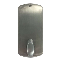
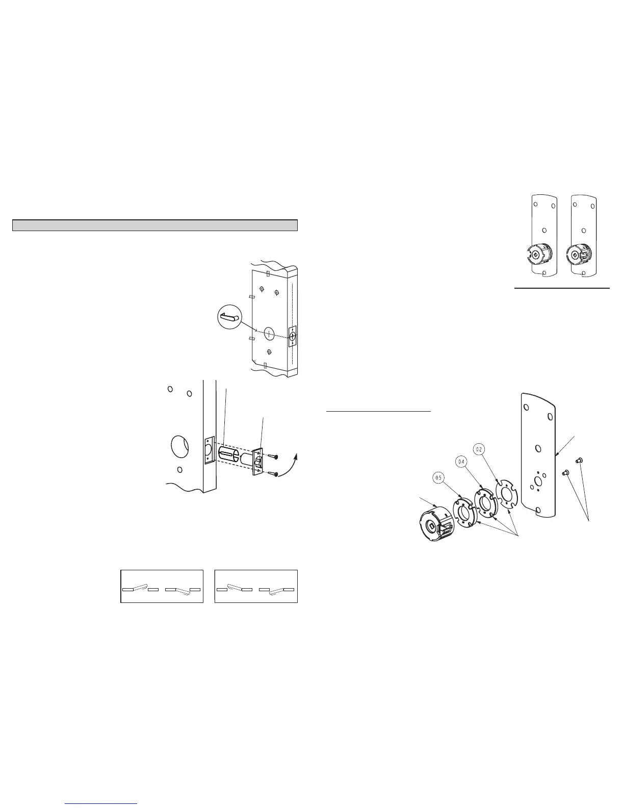
Screws
Cylindrical Unit
Assembly
7
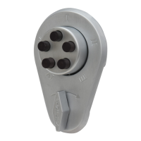
B-2 Remove the two connecting screws from the
cylindrical drive unit. Rotate cylindrical drive
unit 180º. Reposition spacer(s) as found before
disassembly. Remount drive unit with the two
connecting screws.
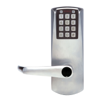
C. DOOR THICKNESS
The cylindrical unit and plate assembly is shipped assembled in factory for 1
3
⁄4"
(44 mm) door thickness (1
1
1
⁄16" [43 mm] to less than 1
7
⁄8" [48 mm]) with 2 spac-
ers "04"; 1 spacer "02" and 2 flat head screws
5
⁄8" (16 mm) LG. For other door
thicknesses, use door thickness table for appropriate spacers and screws
included in the hardware bag.
C-1 Prepare attachment plate and cylindrical drive unit for door thicknesses
less than 1
11
⁄16" (43 mm) or 1
7
⁄8" (48 mm) and above according to the
Door Thickness Table, on the next page.
Correct Position of Spacers
LH Assembly RH Assembly
Cylindrical Drive Unit Position
6
A. DOOR PREPARATION
Note: Drill from both sides of the door to prevent unsightly damage.
A-1 Determine which template fits your E-Plex 2000 installation (either the
2
3
⁄8" [60 mm] Backset or the 2
3
⁄4" [70 mm] Backset).
A-2 Place appropriate paper template (supplied) onto door and
mark for holes. Drill the three
1
⁄2" (13 mm) holes first. Next
drill the 2
1
⁄8" (54 mm) cross bore hole. Drill the 1" (25 mm)
hole last.
A-3 Mortise door edge for latch unit faceplate
3
⁄16" (5 mm)
deep to dimensions shown. Insert latch unit into the
1" (25 mm) hole, making certain that the latch bolt
bevel faces direction of closing door.
A-4 Secure the latch to the door using two 1" (25 mm)
Phillips Mounting screws supplied. Latch unit face-
plate must be flush with door (for doors with 1"
diameter hole, use sleeve on latch).
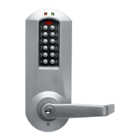
B. LOCK HANDING
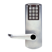
The E-Plex 2000 is a non-handed lock that is preassembled for left-hand
door installations.
B-1 Determine the hand of your door. For Left Hand doors, proceed to section C.
For Right Hand doors, follow steps below.