Do you have a question about the Kaba E-PLEX 2000 Series and is the answer not in the manual?
Lists all components and tools required for the cylindrical lockset installation.
Enumerate all necessary tools for performing the installation steps.
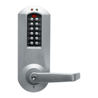
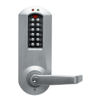
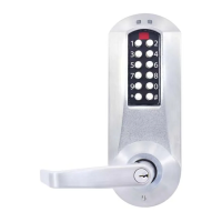
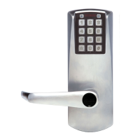
Visual guide identifying and labeling each part of the lock mechanism.
Detailed instructions for preparing the door prior to lock installation.
Procedures for determining and setting the correct handing for the lock.
Guidance on selecting appropriate spacers based on door thickness.
Step-by-step instructions for fitting the lock housings onto the door.
Instructions for mortising the door frame and installing the strike.
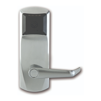
Overview of mortise lock parts, checklist, and exploded views.
Specific tools required for the mortise lock installation process.
Exploded diagram detailing the components of the mortise lock.
Initial steps for installing standard mortise lock assemblies (ASM models).
How to reverse the handing mechanism of a field-reversible mortise lock.
Specific assembly steps for the inside trim of Autodeadbolt ASM mortise locks.
Procedure for preparing the door and installing the mortise lock body.
Guides installation of exterior housing and interior trim for mortise locks.
Steps to reverse the outside lever for specific mortise lock series.
Testing procedures specific to the E-2400 series mortise lock.
Lists compatible exit devices and components for installation with the lock.
Details door preparation steps required for exit device integration.
Guides the combined installation of the lock and exit device assembly.
| Material | Metal |
|---|---|
| Dimensions | Varies by model; see specific product datasheet |
| Handing | Reversible |
| Backset | 2-3/4" or 2-3/8" |
| Key Override | Optional |
| Programming | Via keypad |
| Voltage | 12/24 VDC |
| Strike Adjustment | Yes |
| Compatibility | Standard door preparations |