2
Recommended Spare Parts List
Item No. Item Description
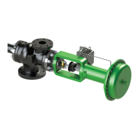
1 Body
2 Diffuser Gasket*
3 Diffuser
4 Bonnet Gasket
5 Bonnet
6 Packing Assembly*
7 Packing Follower*
10 Nozzle Gasket*
11 Nozzle*
12 Spindle*
Spare Parts List
*Items marked with an asterisk are recommended parts to be kept in the end user’s store inventory.
To order spare parts please contact customer service at Kadant Johnson LLC:
• Tel: 269-278-1715
• Email: orders.tr@kadant.com
Parts are normally available in three to four weeks after order.
Always refer to the thermocompressor serial number when ordering parts.
Design
Installation Consideration
The following schematic depicts the recommended installation guideline for the
thermocompressor installation in piping runs:
Thermocompressor mounting position
The preferred installation is vertical with the actuator on top and the discharge pointing down. However, the unit can be mounted
horizontally as well without any restrictions on the axis of rotation. Installation of the unit in an upside-down position (actuator
pointing down and discharge pointing upward) is not recommended.
Allowable forces and moments
The piping should be supported/anchored so that there are no forces translated to the thermocompressor flanges. The
thermocompressor should be supported by a bracket of some type that attaches to the unit itself. A rigid pipe hanger is recommended
and should be placed on the body portion of the thermocompressor. All three connections should have expansion joints on or very
near them to avoid applying pipe stress to the thermocompressor. The other alternative is to support the unit from just one flange.
If mounted vertically it should be the discharge flange, if mounted horizontally it should be the suction flange. If this method is
employed the other two flanges should have expansion joints to isolate them from the rest of the piping system.
Shut-off Plug
It is dangerous to use the shut-off device (actuator) fitted to this thermocompressor as an isolating valve. The actuator is neither
intended nor designed for leak-free closure. Its only purpose is to arrest the flow of high-pressure steam for a short period, during air
failure or plant shutdown, to enable the main steam isolating valve to be closed.
In the event of air failure or plant shut-down, do not rely on the shut-off device fitted to the thermocompressor to give complete
sealing of the high-pressure steam. To maintain the pressure and temperature integrity of the body and diffuser, and in the interest of
safety, the main steam isolating valve must be closed before closing any isolating valves fitted in the suction or discharge line.
 Loading...