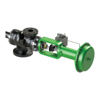
Actuator Removal:
1. Disconnect incoming cable or tubing to the positioner manually
2. Apply 5 to 10 psig air pressure to the actuator to pull the spindle off the seat
3. Disconnect the stem connector on the actuator
4. Release the air pressure
5. Remove the locknut securing the actuator to the motive body
6. The actuator is now free to be removed
Although thermocompressors are normally efficient and trouble-free in operation, there are times when thermocompressors can be subject
to breakdowns. Some knowledge of the correct procedures for locating the most usual causes of trouble could save valuable production.
Most of the attributed reasons for the sub-standard performance can usually be traced to either external or internal causes. Sub-standard
performance can also be classified as either sudden or gradual. A gradual deterioration in performance usually results in a loss of re-
compression, invariably suggesting either erosion or corrosion, whereas a sudden loss of compression will usually suggest an internal
breakage or external cause. Since the external causes of trouble are usually easier to check, they should be investigated first.
When a fault is investigated, it may be prudent to treat as suspect all the gauges fitted, especially Bourdon Tube Type dial gauges.
These gauges should, whenever it is possible, be recalibrated.
External Causes of Poor Performance:
• Low motive steam pressure
• Wet motive steam
• Differential too high
• Incorrect discharge pressure
• Change in load
• Attempting to operate outside the design parameters
When the external causes have been checked and, if they have been found to be trouble-free, check for internal causes of trouble.
Internal Causes of Poor Performance:
• Eroded or corroded internal parts
• Blocked nozzles and/or diffusers
• Cracked or worn parts
• Leakage from the high-pressure area to the low-pressure area (check nozzle gasket)
• Misaligned nozzle and spindle assembly
When you are commissioning a new plant, clogged steam nozzles could also be a source of trouble. If the nozzle inlet is red or black,
look for scale deposits which can be removed by very careful scraping and subsequent polishing.
Always conduct a fault-finding exercise in a logical and systematic manner, eliminating one possible cause at a time. This will save you
time and the mechanism of faults will be more clearly understood and could be of invaluable help at some future date.
6
Operation and Maintenance
Troubleshooting and Operating Problems
Disassembly Procedures
Bonnet and Spindle Removal:
1. Remove the nuts securing the bonnet to the body; the bonnet, spindle, and spindle guide can now be removed
from the body
2. Remove the two nuts securing the packing flange to the bonnet
3. Remove the packing flange and packing follower by sliding them over the spindle stem
4. Remove the spindle from the bonnet
5. Remove the packing from the bonnet
6. Remove the spindle guide if worn or damaged
Nozzle Removal:
1. Remove the cap screws securing the nozzle to the body
2. The nozzle can now be removed from the body as well as the nozzle gasket
3. Clean nozzle gasket face thoroughly
Diffuser Removal:
1. Remove the nuts securing the diffuser to the body
2. The diffuser can now be removed from the body as well as the diffuser gasket
 Loading...