ECO-DRAIN 21, 21 PLUS
ECO-DRAIN 21 PLUS
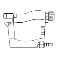
Note before wiring:
The mains voltage must correspond
to the permissible voltage on the type
plate (1)!
Please ensure that the installation is
carried out according to the valid
regulations.
Please assign terminals as indicated!
Remove screws (5) and lift off housing
top (4) paying attention to the cable.
Unplug connector (7) from terminal on
control PCB (8).
Fit board holder (2) with power supply
board into the housing top (4).
Connect power supply
Unscrew union nut (6) and remove
blanking disk (12)
Guide a 3-core cable (9) for power
supply through screwed cable fitting
and connect to board terminal PS.
Terminal assignment in the case of Vac
devices:
L = phase conductor (black)
N = neutral conductor (blue)
PE = protective conductor (green/yellow)
In the case of Vdc devices (direct cur-
rent) the poling can be chosen as de-
sired: + 24 Vdc
Potential-free alarm contact
Guide 3-core cable (10) through cable
fitting (11) and connect to board termi-
nal AS (changeover contact).
N.C.COM:
Contact closed during malfunction or
power failure (fail-safe principle).
N.O.COM:
Contact closed during normal operation.
External test button (optional)
Use separate connecting lead!
Assembly
Pull cables (9+10) tight and screw
down cable fittings (6+11)
Move board holder (2) with power
supply board upwards (must click into
place).
Plug connector (7) to terminal on con-
trol PCB (8).
Slide housing top (4) with board holder
(2) into the guiding grooves.
Tighten the screws (5).
english français nederlands
ECO-DRAIN 21 PLUS
Elektrische installatie:
Toelaatbare voeding op typeplaatje
(1) aflezen en zeker nakomen!
Installatiewerkzaamheden altijd
volgens de geldende voorschriften
uitvoeren.
Let op de juiste elektrische aansluiting!
Bovensdeksel (4) demonteren door
lasdraaien van schroeven (5) (op ka-
bel letten)
Stekker (fletcable) (7) van print (8)
halen
Printmoduul (2) met de voedingsprint in
het huis monteren.
Spanning aansluiten
Wartels (6) losdraaien en afdichtingen
(12) verwijderen
Kabel (9) door wartels en bestemde
gaten doorvoeren en op contact PS
ansluiten
Elektrische aansluiting
L = zwart
N = blauw
PE = groengeel ( aarde)
Bij 24 Vdc-apparaten (gelijkspanning)
is het volgende gewenst: ± 24Vdc
Potentiaalvrij contact
Kabel (10) door wartels (11) en be-
stemde gaten doorvoeren en op con-
tact AS aansluiten (wisselaar)
N.C.COM:
Contact gesloten bij storing of stroom-
storing (failsafe-modus)
N.O.COM:
Contact gesloten bij normale funktie
Externe test-schakelaar (optie)
Separate aansluithandleiding raad-
plegen!
Montage
Kabels (9+10) aantrekken en wartels
(6+11) vastdraaien
Printmoduul (2) met voedingsprint vast
zetten tot hij klikt
Stekker (fletcable) (7) op print (8) ste-
ken
Bovendeksel (4) met printmoduul (2) in
huis schuiven
Schroeven (5) vastdraaien
ECO-DRAIN 21 PLUS
A noter avant l'installation électrique:
Seule la tension secteur mentionnée
sur la plaque signalétique (1) est
admissible !
Réaliser les travaux d'installation
conformément à VDE 0100.
Respecter l'affectation des bornes !
Desserrer les vis (5) et retirer le capot
du boîtier (4) (attention au câble)
Débrancher le connecteur d'alimentation
(7) sur la carte de commande (8).
Pour accéder aux borniers, faire pivoter
sur le capot (4) la carte d'alimentation
secteur (2).
Brancher l'alimentation secteur
Desserrer l'écrou (6) du presse-étoupe
et retirer l'obturateur (12)
Enfiler le câble à 3 conducteurs (9)
assurant l'alimentation électrique, à tra-
vers le presse-étoupe, et le raccorder
au bornier PS de la carte.
Affectation des bornes sur les appareils
Vac (alimentés en alternatif)
L= phase (noir)
N= neutre (bleu)
PE= terre (vert/jaune)
Sur les appareils 24 Vdc (alimentés en
continu) la polarité n'a pas d'importance:
± 24Vdc
Contact d'alarme, sans potentiel
Enfiler un câble à 3 fils (10), (à 5 fils
en cas d'utilisation d'un bouton TEST
externe), à travers le presse-étoupe
(11) et le raccorder au bornier AS de
la carte (inverseur)
N.C.COMMON:
Contact fermé en cas de dysfonctionne-
ment ou de coupure de courant (sécuri-
té positive)
N.O.COMMON:
Contact fermé en fonctionnement normal
Bouton Test externe (en option)
Suivre les instructions de branchement
séparées !
Montage
Tendre les câbles (9+10) et serrer les
presse-étoupes (6+11)
Pivoter la carte d'alimentation (2) (jusqu'à
l'encliquetage)
Enficher le connecteur d'alimentation
(7) sur la carte de commande (8).
Monter le capot du boîtier (4) en enga-
geant la carte (2) dans les rails de
guidage.
Serrer les vis (5)
 Loading...