16
Service and Repair Manual
Model 710/760
Fig. 19
710MV DISMANTLING
Fig. 18
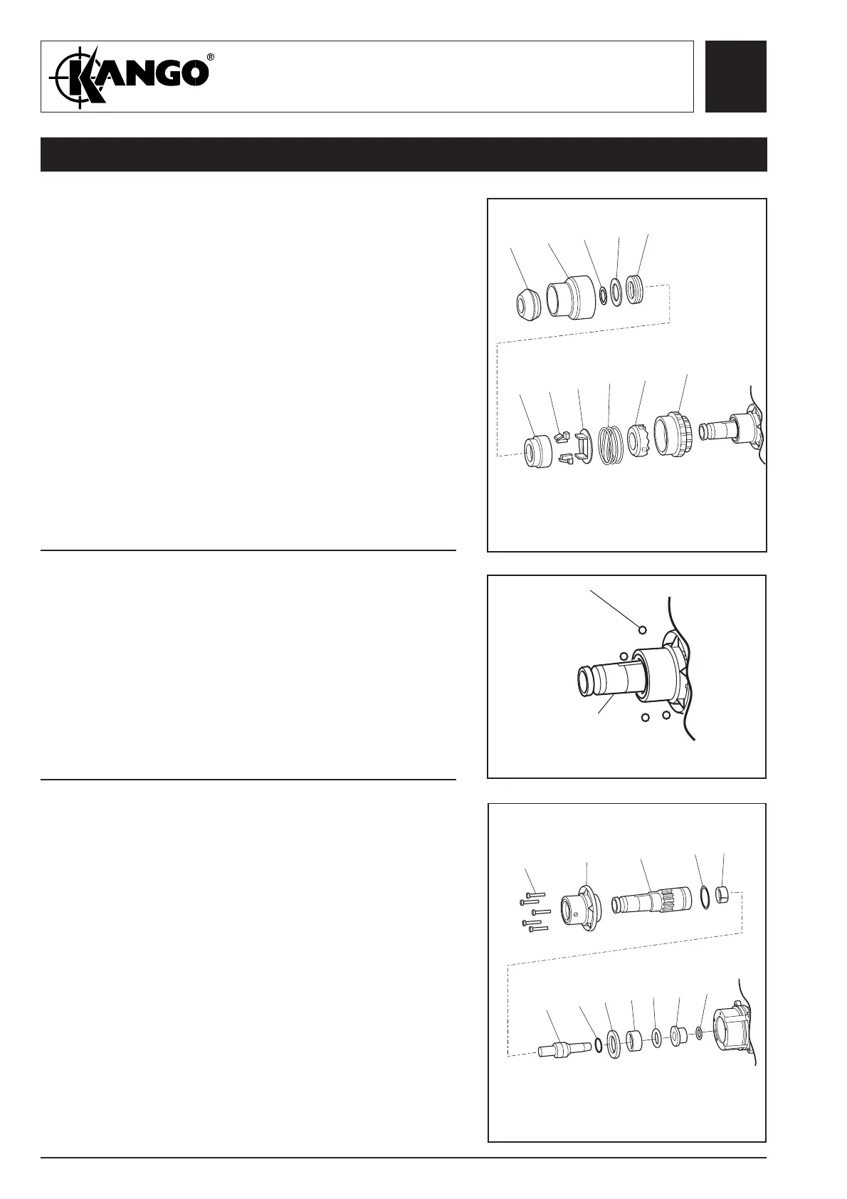
Removing
the chuck
1. Remove four balls (99).
Dismantling
the chuck
1. Dismantle chuck by removing end cap (118)
remove chuck cover (117) and the following
items:
- circlip (116)
- buffer stop (115)
- buffer (114)
- chuck (113)
- latches (112)
- latch plate (111)
- latch spring (110)
- lock plate (109)
- lock chuck (108)
113
112
111
110
109
108
118
117
116
115
114
99
Fig. 20
Dismantling
the driver
assembly
1. Remove five screws (100), nosepiece (98) and the
following items from driver (97):
- O-ring (88)
- catcher (89)
- buffer ring (90)
- transfer ring (91)
- junk ring (92)
- seal (93)
- anvil (94)
- junk ring (95)
- O-ring (96)
100
98
97
96
95
94
93
92
91
90
89
88
Service and Repair Manual
Model 710KV/710BV
97
 Loading...