English 7
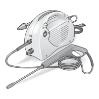
Description of the device
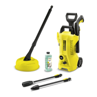
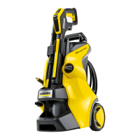
The maximum amount of equipment is described in
these operating instructions. Depending on the model
used, there are differences in the scope of delivery (see
packaging).
For the illustrations, refer to the graphics page
Illustration A
1 Transport wheel
2 Storage for spray lance
3 Storage / parking position for high-pressure gun
4 Power Control spray lance dirt grinder for stubborn
dirt, pressure level: HARD
5 Click-Vario Power Power Control spray lance for the
most common cleaning tasks, pressure levels:
HARD / MEDIUM / SOFT / MIX
6 Power Control high-pressure gun
7 Clamp for connecting / disconnecting the high-pres-
sure hose
8 High-pressure gun lever
9 High-pressure gun lock
10 Trigger "0/OFF" / "I/ON"
11 Mains connection with mains plug
12 Storage hook for power cord
13 Carrying handle
14 Transport handle, telescoping
15 Quick coupling for high-pressure hose
16 Type plate
17 High-pressure hose
18 Water connection with integrated sieve
19 Detergent suction hose
20 Water connection coupling
21 **Garden hose with commonly available coupling
– Fabric reinforced
– Diameter of at least 1/2 inch (13 mm)
– Length at least 7.5 m
22 *Washing brush, suitable for working with deter-
gents
23 *Foam nozzle for powerful detergent foam
24 *Detergent container
* optional, ** zusätzlich erforderlich
Safety devices
몇 CAUTION
Missing or modified safety devices
Safety devices are provided for your own protection.
Never modify or bypass safety devices.
Power switch
The power switch prevents unintentional operation of
the device.
High-pressure gun lock
The lock locks the lever of the high-pressure gun and
prevents the device from starting unintentionally.
Auto-stop function
If the lever of the high-pressure gun is released, the
pressure switch turns off the pump and the high-pres-
sure jet stops. The pump switches on again when the le-
ver is pressed.
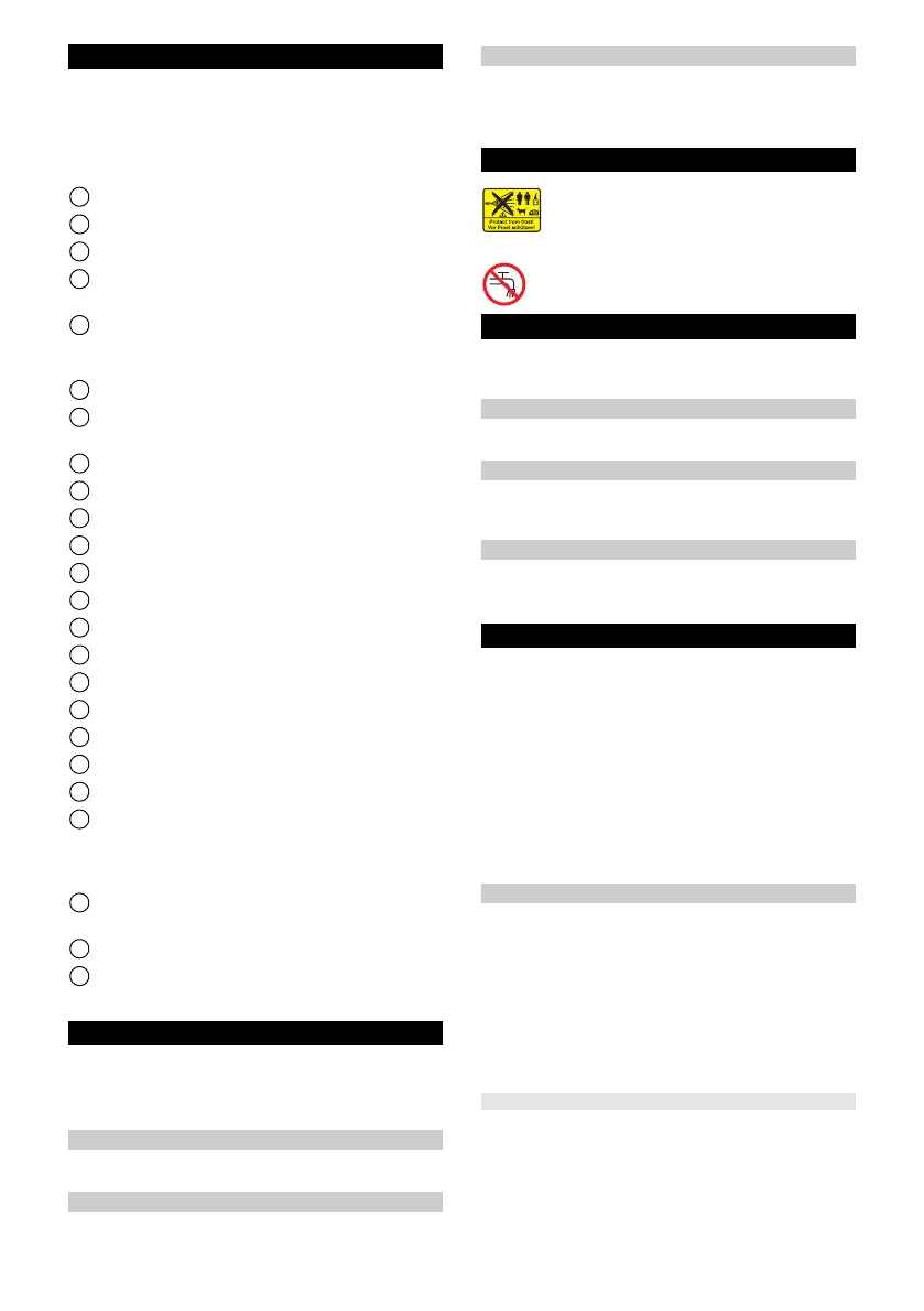
Symbols on the device
Assembly
For the illustrations, refer to the graphics page.
Fit the supplied loose parts onto the device before start-
ing up the device.
Fitting the wheels
1. Fasten and secure the wheels to the device.
Illustration B
Installing the handles
1. Attach the transport handle.
2. Attach the carrying handle.
Illustration C
Installing the water connection coupling
1. Screw the water connection coupling onto the water
connection on the device.
Illustration D
Initial startup
1. Place the device on a flat and level surface.
2. Insert the high-pressure hose into the quick coupling
until it audibly latches into place.
Illustration E
3. Press the clamp for the high-pressure hose together
and pull out of the high-pressure gun.
Illustration F
4. Insert the high-pressure hose into the high-pressure
gun.
5. Press the clip in until it latches into place.
6. Check for a secure connection by pulling on the
high-pressure hose.
7. Plug the mains plug into a mains socket.
Water supply
For the connection values, see the type plate or chapter
Technical data.
Observe the water distribution company regulations.
ATTENTION
Damage through contaminated water
Contamination in the water can damage the pump and
the accessories.
KÄRCHER recommends using the KÄRCHER water fil-
ter for protection(special accessory, order number
4.730-059).
Connection to the water line
ATTENTION
Hose coupling with Aquastop on the water connec-
tion of the device
Damage to the pump
Never use a hose coupling with Aquastop on the water
connection of the device.
You can use an Aquastop coupling on the tap.
Do not aim the high-pressure jet may at per-
sons, animals, live electrical equipment or
the device itself.
Protect the device against frost.
The device may not be connected to the
public drinking water network.