3
ASSEMBLY
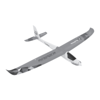
Wing
1. Locate the steel wire wing joiner (note the “V” shape ensuring the correct
wing dihedral) with the plastic adapter and slide both wing halves onto
the joiner.
2. Secure the wing halves using the wing joiner plate.
3. Use the supplied Y-cables to connect the aileron servos and LED light ca-
bles:
A. A radio featuring only one aileron channel (like the T8FB supplied
in the RTF set): Connect both two aileron servos (connector label “AILE”)
to one Y-cable and both two LED light cables (labelled “LED”) to another
Y-cable. The aileron Y-cable is to be connected to the aileron channel of
your receiver (CH1 in the case of T8FB); the LED light Y-cable could be con-
nected to any unused channel of your receiver (the LEDs are just powered
by the receiver; they are not remote controlled by the radio).
B: A radio featuring 2 independent aileron servo channels: Connect
one aileron servo and one LED light to each Y-cable; connect the Y-cables
to the respective aileron channels of your receiver (typically, CH1 and CH5
or CH6 – it depends on the transmitter and its setting – please refer to the
instruction manual of your radio).
4. Secure the wing using two 2.5x15 mm screws to the fuselage.
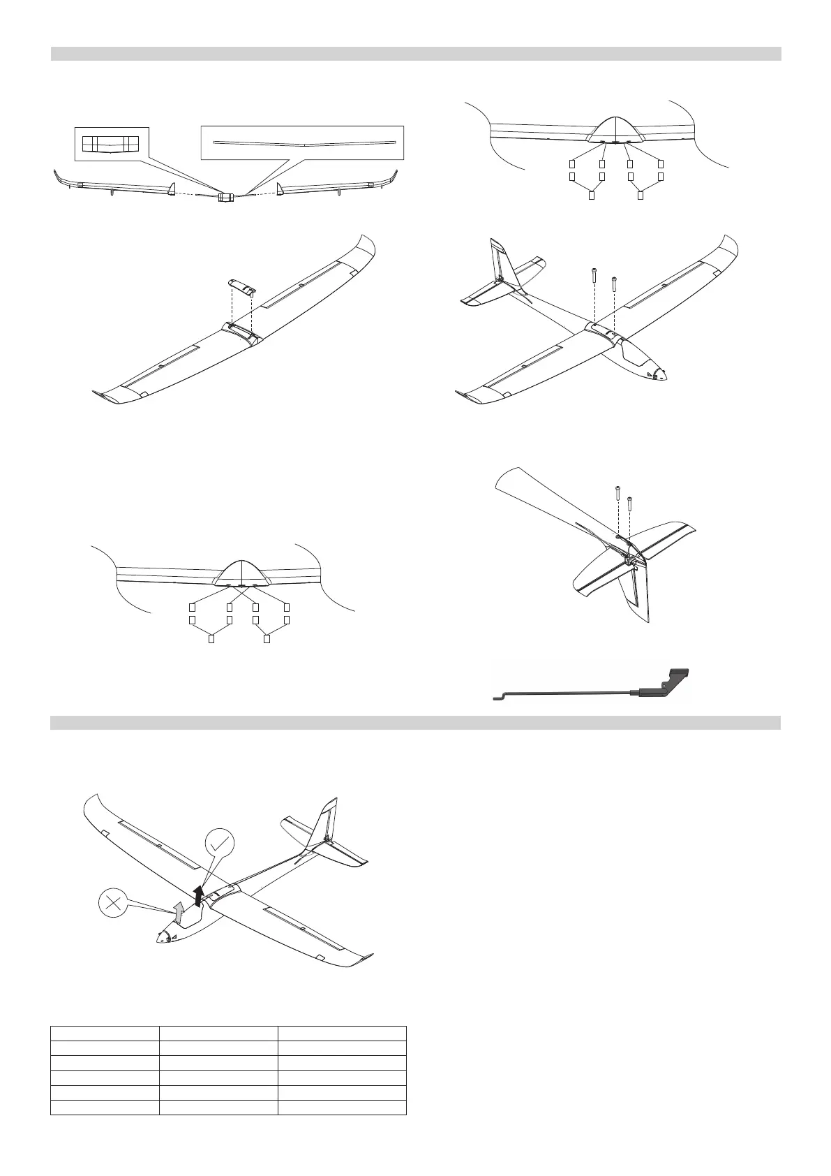
Tail Feathers
1. Put together the vertical and horizontal tailplane and secure them using
two 2.5x15 mm screws to the fuselage.
2. Attach the plastic quick links of the elevator and rudder pushrods to the
outer hole in the respective elevator and rudder horns.
RC SET INSTALLATION
Now you have to install/connect your receiver, servos and electronic speed
controller (ESC).
1. Remove the canopy; lift the rear part up to disengage the magnetic lock.
2. Following you radio instruction manual connect the servos, ESC and LED
light cables to your receiver – the table shows the channel assignment of
the T8FB radio supplied in the RTF kit:
Connector Label Function Receiver Channel (T8FB)
AILE Ailerons CH1
ELEV Elevator CH2
ESC Throttle CH3
RUDD Rudder CH4
LED LED Lights CH5
3. Put your receiver into the fuselage under the wing seat; you can secure it
using a strip of Velcro to the fuselage.
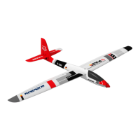
4. The ight battery pack is to be inserted into the nose of your ALPHA 1500
V2 and secured by the Velcro tape to the plywood battery trail - the exact
position of the battery pack will be determined later during the Centre of
Gravity position check.
CAUTION: Always turn on your transmitter rst and only then connect
the ight pack to the ESC. From now on always handle your model as if
the motor might burst into life and the propeller start to spin anytime!
AILE
Ailerons (CH1)
LED
LED (CH5-8)
AILE
Aileron1 + LED
LED
Aileron2 + LED
AILELED
2.5x15 mm
2.5x15 mm