Do you have a question about the KAZE APPLIANCES SNP100 and is the answer not in the manual?
Use the ventilation fan only as intended by the manufacturer.
Ensure power is off at the service panel before servicing or cleaning.
Installation and wiring must be done by qualified persons per applicable codes.
Ensure sufficient air for proper combustion and exhaust of gases.
Do not damage electrical wiring or hidden utilities when cutting or drilling.
Ducted fans must always be vented to the outdoors.
Acceptable for use over tub/shower with GFCI-protected circuit.
This unit must be properly grounded.
For general ventilating use only; do not exhaust hazardous materials.
Designed for ceilings up to 12/12 pitch; do not mount in a wall.
Keep unit clean from dust to prevent motor bearing damage and impeller imbalance.
Refer to the specification label on the product for further information.
Motor is permanently lubricated and requires no oiling. Replace motor if bearings make noise.
Refer to "CONNECT ELECTRICAL WIRING" section for details.
Do not use the fan in or above a cooking area.
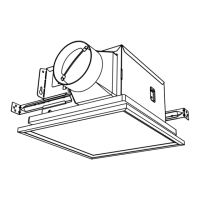
Two ways to connect ductwork to a factory-shipped unit.
Housing mounted to I-joists.
Housing mounted to joists.
Housing mounted to truss.
Steps to attach housing to joist or I-joist using screws.
Steps for mounting using holes and hanger bar between framing.
Steps for mounting housing to I-joist using hanger bar.
Steps to install duct and fix blower assembly to housing.
Connect round ductwork, seal connections, and use tape.
Steps to remove wire panel and blower assembly before installation.
Enlarge ceiling opening and connect ductwork and wiring.
Instructions on mounting fan housing using additional holes or flange.
Pull existing ducting through opening and connect to duct connector.
Final step to install the blower assembly into the housing.
Connect 120 V AC house wiring to the fan using UL-approved connectors.
Attach grille to fan housing by inserting light plug and securing grille springs.
List of service parts with part numbers, names, and quantities.
Details on components included in the blower assembly.
Identification of different screw types used in assembly.
Instructions for replacing the blower assembly.
Covers defects in workmanship or materials for 12 months from purchase.
Details damages and issues not covered by the warranty.
Disclaims implied warranties and limits liability for incidental damages.
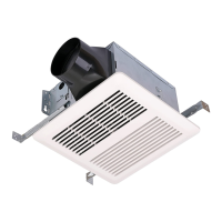
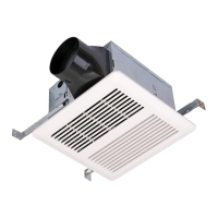
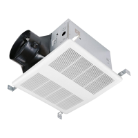
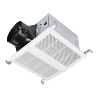
This document outlines the installation, operation, and maintenance of a KAZE Ventilation Fan, specifically models SNP100 and SNP100L9. This device is designed to provide ventilation by exhausting air from indoor spaces to the outdoors, contributing to improved air quality and comfort.
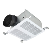
The primary function of the KAZE Ventilation Fan is to remove stale air, odors, and moisture from a room, replacing it with fresh air. This is achieved by drawing air from the indoor environment and expelling it through a duct system to the outside. The fan is particularly useful in areas where moisture and odors tend to accumulate, such as bathrooms, to prevent issues like mold growth and unpleasant smells. For models like the SNP100L9, the unit also incorporates a light, providing both illumination and ventilation from a single ceiling fixture. The fan operates by means of a motor that drives an impeller, which creates the airflow necessary for ventilation. The design emphasizes quiet and efficient operation, aiming to minimize noise while effectively moving air.
The KAZE Ventilation Fan is intended for general ventilating use and is specifically designed for ceiling installation. It is suitable for use in ceilings with a pitch up to 12/12 (45-degree angle), and the duct connector must point upwards. A critical usage feature is its suitability for installation over a tub or shower, provided it is connected to a Ground Fault Circuit Interrupter (GFCI)-protected branch circuit, ensuring safety in wet environments. However, it is explicitly stated that the unit should not be used to exhaust hazardous or explosive materials and vapors, nor should it be installed in a cooking area or mounted in a wall.
The installation process offers flexibility, with options for mounting to I-joists, standard joists, or trusses. The fan requires proper ductwork to vent to the outdoors, and the manual emphasizes the importance of using the shortest, straightest duct routing possible for optimal performance, airflow, and energy efficiency. Insulated flexible ducting is recommended for the quietest operation, and all ductwork connections must be sealed airtight to prevent air leakage. The unit is designed to be grounded for electrical safety.
For models with a light feature, the wiring diagram illustrates how to connect both the fan and the light to separate switches, allowing independent control of each function. This provides users with the flexibility to use the light without the fan, or vice versa, depending on their needs. The grille assembly is designed for easy attachment to the housing, securing it flush with the ceiling.
Maintaining the KAZE Ventilation Fan is straightforward and designed to ensure long life, quiet operation, and an attractive appearance. Regular cleaning is recommended, which involves lowering or removing the grille and vacuuming the interior of the unit using a dusting brush attachment. This helps prevent the buildup of dust and debris that can impede airflow and increase noise.
A significant maintenance feature is that the motor is permanently lubricated and does not require oiling. This eliminates a common maintenance task associated with many mechanical devices. If the motor bearings begin to make excessive or unusual noises, it indicates a need for replacement. In such cases, the manual advises replacing the motor with the exact service motor, and the impeller should also be replaced at the same time to ensure continued optimal performance.
The manual also provides instructions for replacing specific service parts, such as the blower assembly, motor, and impeller, should they become defective. It outlines the steps for removing the blower assembly from the housing to access and replace broken parts. A warning is included to ensure the fan is switched off from the supply mains before any replacement work is undertaken, prioritizing safety.
The design of the unit, particularly the blower assembly, allows for removal to facilitate access for maintenance or replacement of internal components. This modular approach simplifies repairs and extends the overall lifespan of the ventilation fan.
| Model | SNP100 |
|---|---|
| Category | Fan |
| Power | 60W |
| Phase | Single |
| CFM | 1500 |
| Frequency | 60Hz |
| Speed Settings | 3 |
| Blade Size | 16 inches |
| Material | Plastic |
| Color | White |