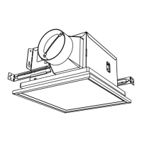
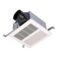
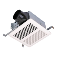
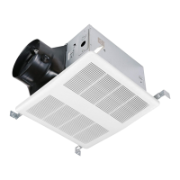
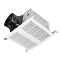
VENTILATION FAN
WARNING
Models: SNP100L9
SNP100HL9
READ AND SAVE THESE INSTRUCTIONS
Installer: Leave this manual with the homeowner.
CAUTION
CLEANING & MAINTENANCE
OPERATION
TO REDUCE THE RISK OF FIRE, ELECTRIC SHOCK, OR INJURY TO PERSONS, OBSERVE THE FOLLOWING:
1. Use this unit only in the manner intended by the manufacturer. If you have questions, contact the
manufacturer at the address or telephone number listed in the warranty.
2. Before servicing or cleaning unit, switch power off at service panel and lock the service disconnecting
means to prevent power from being switched on accidentally. When the service disconnecting means
cannot be locked, securely fasten a prominent warning device, such as a tag, to the service panel.
3. Installation work and electrical wiring must be done by a qualified person(s) in accordance with all
applicable codes and standards, including fire-rated construction codes and standards.
4. Sufficient air is needed for proper combustion and exhausting of gases through the flue (chimney) of
fuel burning equipment to prevent backdrafting. Follow the heating equipment manufacturer’s guideline
and safety standards such as those published by the National Fire Protection Association (NFPA), and
the American Society for Heating, Refrigeration and Air Conditioning Engineers (ASHRAE), and the
local code authorities.
5. When cutting or drilling into wall or ceiling, do not damage electrical wiring and other hidden utilities.
6. Ducted fans must always be vented to the outdoors.
7. Acceptable for use over a tub or shower when connected to a GFCI (Ground Fault Circuit Interrupter) -
protected branch circuit (ceiling installation only).
8. This unit must be grounded.
1. For general ventilating use only. Do not use to exhaust hazardous or explosive materials and vapors.
2. This product is designed for installation in ceilings up to a 12/12 pitch (45 degree angle). Duct connector must point up. DO NOT MOUNT THIS
PRODUCT IN A WALL.
3. To avoid motor bearing damage and noisy and/or unbalanced impellers, keep drywall spray, construction dust, etc. off power unit.
4. Please read specification label on product for further information and requirements.
For quiet and efficient operation, long life, and attractive appearance - lower or remove grille and vacuum interior of unit with the dusting brush attach-
ment.
The motor is permanently lubricated and never needs oiling. If the motor bearings are making excessive or unusual noises, replace the motor with the
exact service motor. The impeller should also be replaced.
See “CONNECT ELECTRICAL WIRING” for details.
To adjust the “H”:
1. Disconnect power at service entrance.
2. Through the grille, locate the slot marked “H”.
3. Carefully rotate the “H” adjustment toward “+” or “-”.
4. Turn on power and check operation by turning on the shower or other humidity source until the fan turns on.
5. Repeat above steps if necessary.
When the temperature changes, humidity sensor values will have deviation.
The humidity-sensing fan uses a sophisticated humidity sensor that responds to: (a) rapid increases in humidity or (b) humidity above a user-adjustable
set-point (30%-80% relative humidity). The humidity sensor may occasionally turn the fan ON when environmental conditions change. If the fan
continuously responds to changing environmental conditions, “H” (means “humidity”) adjustment may be required. This figure is factory-set for about
80% (Ambient temperature of 25℃).
SENSITIVITY ADJUSTMENT
The “H” has been factory set for most shower applications. However, if the fan is in a tub area or is being used for dampness control, the “H” may need
to be increased toward maximum “+”. If the control is responding too often to changing environmental conditions, movement toward less “-” “H” may be
required.
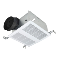
HUMIDITY SENSOR MODEL: SNP100HL9
Cod: 0060303190-B