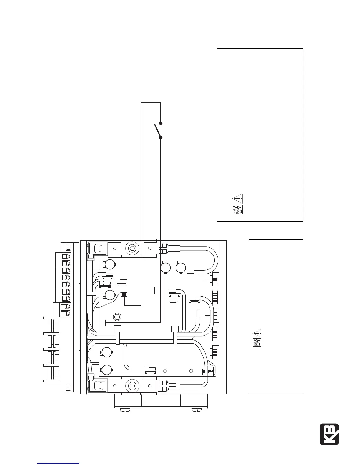
Inhibit Switch
(Close to Coast-to-Stop)
(Open to Run)
Note: KBPB shown. The KBCC-R uses the same PC board.
P2
P3
L2
F+
P1
I1
A-
B
F-
A+
I2
T
L1
(A40150) – Rev. C – 7/2006
Print Code
KB ELECTRONICS, INC.
12095 NW 39th Str
eet, Coral Springs, FL 33065-2516 • (954) 346-4900 • F
AX (954) 346-3377
Outside Florida Call Toll Free (800) 221-6570 • info@kbelectronics.com
www.kbelectronics.com
KBPB & KBCC-R SUPPLEMENTAL INFORMATION
SAFETY WARNING!
This drive contains electronic Start/Stop circuits which can be used to
start and stop the drive. However
, these circuits are never to be used
as safety disconnects since they are not fail-safe. Use only the AC
line for this purpose. Be sur
e to follow all instructions car
efully. Fire
and/or electrocution can result due to improper use of this product.
MOUNTING INSTRUCTION FOR CHASSIS & IP-20 CONTROLS
WARNING! This control must be mounted in an enclosure. Care
should be taken to avoid extreme hazardous locations where
physical damage to the control can occur due to moisture, metal chips, dust,
and other contamination including corrosive atmosphere. If such contamination
is present, special enclosures may be required such as NEMA type 4X. Failure
to observe these instructions could cause an electrical shock, fire, or explosion
in this product or the products used with this product. Do not use this control
in an explosion-proof application. You must read the Safety Warning which
accompanies this product.
The latest versions (11/2000) of the KBPB and KBCC-R controls do not contain
Inhibit terminals on the terminal block. The Inhibit feature is available, however,
by wiring a switch or contact to the I1 and I2 QD terminals on the PC board.
The control uses the S2 terminal for brake-to-stop operation (open to stop,
close to run). If the application requires coast-to-stop operation, connect the
Inhibit Switch as shown below.
One side of the Inhibit Switch connects to the new piggyback I1 QD Terminal.
The other side of the Inhibit Switch connects to the I2 QD Terminal (or the F-
terminal on Terminal Block TB2). It is recommended that the Inhibit Switch wires
be routed (and secured with wire ties) with other signal wires (S1, S2, S3, etc.).
Do not route the Inhibit
wires with AC line or
motor wires unless
shielded cables are used.