EasyManua.ls Logo

KB Electronics KBPW-240D User Manual

KB Electronics KBPW-240D
18 pages
To Next Page IconTo Next Page
Page #1 background imageLoading...
Page #1 background image
.%3:',QVWDOODWLRQDQG2SHUDWLRQ0DQXDO5HY$
6XSSOHPHQWDO,QIRUPDWLRQ
&KDQJHVWR:LULQJ6HFWLRQ,,,*RQ3DJH
G. Remote Start/Stop Switch Connections
The control is supplied with a prewired Start/Stop Switch with a normally open "NO"
stop contact. Jumper J6 is factory set to the "NO" position.
For remote 3-wire Start/Stop Switch with a normally closed "NC" stop contact, connect
the switch as shown in Figure 7A, below. Set Jumper J6 to the "NC" position.
Figure 7A
Remote 3-Wire Start/Stop Switch
with Normally Closed Stop Contact
START
STOP
&KDQJHVWR:LULQJ6HFWLRQ,,,.RQ3DJH
K. Enable Connection
Wire the Enable contact to Terminals "EN1" and "EN2" of Terminal Block TB3 as
shown in Figure 10A, below.
The Enable is used to electronically start and stop the control. When the Enable
contact is closed, the control will accelerate to the Main Speed Potentiometer setting.
When the Enable contact is opened, the control will coast to stop.
Note: The contact must be isolated from the AC line and Jumper J7 must be removed.
Figure 10A
Enable Switch Connection
WARNING! Disconnect main power when making connections to the drive.
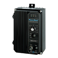
The following information and instructions are to be used as a supplement to the
KBPW-240D Installation and Operation Manual Rev. A (Part No. A40360). The manual
must be read and understood before attempting to operate this control.
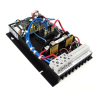
The PC board has been upgraded to include provision for normally open or normally
closed stop contacts and to connect an Enable switch. The General Performance
Specifications have not changed.
Jumper J6 (Stop Switch type "NO" or "NC" Selection) and Jumper J7 (Enable
Selection) have been added. Enable terminals have been added to Terminal Block
TB3. Also, Figures 7A and 10A have been added.
&KDQJHVWR7DEOHRI&RQWHQWVRQ3DJHLL
Figure
Page
7A Remote 3-Wire Start/Stop Switch with Normally Closed Stop Contact ..................8
10A Enable Switch Connection .....................................................................................9
ENABLE SWITCH
Page 1 of 2 Page 2 of 2
KB Electronics, Inc.
(A42140) - Rev. A00 - 3/22/2005 - Z3570A00
Question and Answer IconNeed help?

Do you have a question about the KB Electronics KBPW-240D and is the answer not in the manual?

KB Electronics KBPW-240D Specifications

General IconGeneral
BrandKB Electronics
ModelKBPW-240D
CategoryControl Unit
LanguageEnglish

Summary

Supplemental Information

Remote Start/Stop Switch Connections

Details on connecting a remote 3-wire start/stop switch with a normally closed stop contact.

Enable Connection

Instructions for wiring an Enable switch to terminals EN1 and EN2 for control operation.

General Safety Warnings

Introduction to KBPW-240D Control

Wiring Instructions Overview

Power Connection Details

Connects AC line to TB1 terminals and ground wire to green ground screw.

PM Motor Wiring

Connects PM motor armature to TB1 terminals A1 and A2. Check jumper J3.

Shunt Wound Motor Wiring

Connects shunt wound motor armature and field wiring to TB1 and TB2 terminals.

Motor Current Selection

Trimpot Settings Overview

Diagnostic LED Status

Start/Stop Switch Operation

Remote Start/Stop Switch Connections

Run Relay Connection

Voltage Following Speed Control

Inhibit Connection

Enable Connections

DC Tach-Generator Connection

Setting Selectable Jumpers

Motor Voltage Selection (J1)

Setting jumper J1 for 90V or 180V motor voltage selection.

Motor Current Selection (J2)

Setting jumper J2 for 7.5A or lower motor current settings.

Current Limit Mode Selection (J3)

DC Tach-Generator Voltage Selection (J1 & J4)

Run Relay Output Mode Selection (J5)

Mounting Instructions

Operation and Startup

AC Line Fusing Recommendations

Trimpot Adjustments

Acceleration (ACCEL) Adjustment

Setting the acceleration time from minimum to maximum speed using the ACCEL trimpot.

Deceleration (DECEL) Adjustment

Setting the deceleration time from maximum to minimum speed using the DECEL trimpot.

Maximum Speed (MAX) Adjustment

Setting the maximum motor speed using the MAX trimpot.

Minimum Speed (MIN) Adjustment

Jog Speed (JOG) Adjustment

Current Limit (CL) Adjustment

Timed Current Limit (TCL) Adjustment

Non-Timed Current Limit (NTCL)

IR Compensation (IR) Adjustment

Diagnostic LED Indicators

Optional Accessories

Limited Warranty Information

Related product manuals