For motors of lower amper-
age, set jumper J2 to the cor-
responding position for the
motor being used. See
Figure 13 on page 9 and
Table 5.
Note: For low (L) motor cur-
rent settings (0.8A, 0.5A,
0.4A, 0.3A, and 0.2A), it is
necessary to remove resis-
tor R35 by cutting it out of the
circuit. Cut the leads at the
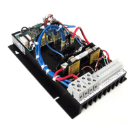
locations shown in Figure 14.
WARNING! Disconnect AC line before cutting out resistor R35. Use an insu-
lated cutter and wear safety glasses.
C. Timed and Non-Timed Current Limit
Selection (J3) –
Jumper J3 is factory set
to “TCL” position for timed current limiting
operation. See Figure 15. For non-timed
current limiting operation, set jumper J3 to
“NTCL” position.
TCL (Timed Current Limit) – When
jumper J3 is set to “TCL” position, the con-
trol will go into “STOP” after it is in over-
load for a predetermined amount of time
(set by the TCL trimpot).
Resetting the Control After TCL – To reset the control after it has gone into TCL,
momentarily set the Start/Stop switch to “START” position or disconnect and reconnect
the AC line. If an On/Off AC Line Switch is installed, set it to “OFF” position and then back
to “ON” position. If the Start switch is jumpered (START and COM terminals connected),
the control must be restarted by disconnecting and reconnecting the AC line.
10
FIGURE 14 – REMOVING RESISTOR R35
1/2, (0.37)
SCR Rated Motor Horsepower
HK, (kW)
PWM Rated Motor Horsepower
HP, (kW)J2 Setting
(Amps DC)
130 Volts DC Motors
1/4, (0.18)
1/2, (0.37)
90 Volts DC Motors 180 Volts DC Motors 220Volts DC Motors
7.5
5.0
3.5
2.5
1.7
0.8*
3/4, (0.5)
1/2, (0.37)
1/3, (0.25)
1/4, (0.18)
1/6, (0.1)
1/12, (0.06)
0.5*
0.4*
0.3*
0.2*
1/20, (0.04)
1/20, (0.04)
1
1
⁄2, (1)
1/25, (0.03)
1/30, (0.02)
1/50, (0.01)
1, (0.75)
3/4, (0.5)
1/3, (0.25)
1/6, (0.1)
1/10, (0.08)
1/12, (0.06)
1/15, (0.05)
1/25, (0.03)
1, (0.75)
3/4, (0.5)
1/2, (0.37)
1/3, (0.25)
1/4, (0.18)
1/8, (0.09)
1/15, (0.05)
1/20, (0.04)
1/25, (0.03)
1/30, (0.02)
2, (1.5)
1
1
⁄2, (1)
1, (0.75)
3/4, (0.5)
1/6, (0.1)
1/8, (0.09)
1/10, (0.08)
TABLE 5 – SETTING MOTOR CURRENT (SCR & PWM Motor Horsepower Ratings)
*Note: For low (L) motor current range settings (0.8A, 0.5A, 0.4A, 0.3A and 0.2A), it is necessary to remove resistor R35
by cutting it out of the circuit as shown in figure 14.