Q.1.3 November 2017
Page 4
KE2 EvaporatorEfciency
Quick Start Guide
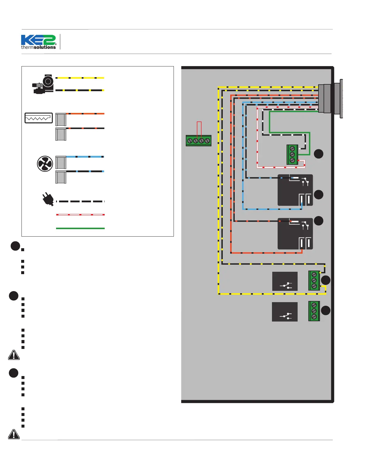
Controller Power
The KE2 Wire Harness wires are pre-stripped (if not using the KE2 Wire
Harness, strip the end of the wires used to provide power to the controller).
Locate a 3-position pluggable connector in the parts kit.
Fasten incoming power to the 3-position pluggable connector*.
Plug the 3-position pluggable connector into board as indicated in Wiring
Schematic.
*All terminal screws should be tightened to 5 ft-lbs.
7
Fan Relay WITH the KE2 Wire Harness
The BLUE wires are used for FAN control.
Locate the blue wire with a black stripe, and the black wire with a blue stripe.
Plug the black wire with a blue stripe into the COM terminal of the Fan Relay
Plug the blue wire with a black stripe into the NO position of the Fan Relay
Fan Relay WITHOUT the KE2 Wire Harness
Strip the end of the 2 wires used for fan control.
Locate 2 female spade connectors in the parts kit.
Crimp on the female spade connectors.
Plug the connectors into the COM and NO positions of the Fan Relay.
Conrm combined fan motor load is not over 10 amps
8
Defrost (Heater) Relay WITH the KE2 Wire Harness
The ORANGE wires are used for the HEATER control.
Locate the orange wire with black stripe, and black wire with orange stripe.
Plug the black wire with orange stripe into the COM terminal.
Plug the orange wire with black stripe into the NO position of Defrost Relay.
Defrost (Heater) Relay WITHOUT the KE2 Wire Harness
Strip the end of the 2 wires used for the defrost control.
Locate the remaining 2 female spade connectors in parts kit.
Crimp on the female connectors.
Plug the connectors into COM and NO positions of the Defrost Relay.
Conrm combined heater load is not over 20 amps.
9
NO NC
COM
NO NC
COM
COM
NC
NO
COM
NC
N0
Solenoid Relay
Defrost
Relay
Fan
Relay
208-240
Power Input
Voltage Jumper
208-240 Default
L1
Ground
L2
COM
NC
NO
COM
NC
N0
Auxiliary Relay
Supply Voltage
8
9
10
11
7
© Copyright 2017 KE2 Therm Solutions, Inc., Washington, Missouri 63090
Yellow with black stripe
16 AWG stripped and retained
Black with yellow stripe (L1)
16 AWG stripped and retained
Blue with black stripe
12 AWG ag connectors
Black with blue stripe (L1)
12 AWG ag connectors
Orange with black stripe
12 AWG ag connectors
Black with orange stripe (L1)
12 AWG ag connectors
Black with white (L1)
16 AWG stripped and retained
White with red (L2/neutral)
16 AWG stripped and retained
Green (Ground)
16 AWG stripped and retained
LLS/Compressor
Defrost Heaters
Fans
Power
Wire Harness Key
 Loading...