EasyManua.ls Logo

KE2 Therm Solutions Evaporator Efficiency User Manual

KE2 Therm Solutions Evaporator Efficiency
20 pages
To Next Page IconTo Next Page
Page #1 background imageLoading...
Page #1 background image
Parts List
The following parts are included in the
KE2 Evaporator Eciency (KE2 Evap) controller kits:
Kit # 20178 with 120/208-240 VAC controller
- OR -
Kit #20222* with Beacon® I or II replacement controller
(4) 3-position screw down terminals (for power in, transducer
and 3A relays)
(1) 120 Voltage jumper
(1) 208-240V Voltage jumper (already on back of KE2 Evap)
(1) 5-position screw down terminal (for EEV)
(8) 2-position screw down terminals (for sensors and digital
input, analog output)
(1) High voltage safety shield
(1) Warranty card
(1) Air sensor mount
(4) wire ties (rated for low temp)
(5) Self-tapping screws
(4) 90 degree quick disconnects
(1) ne thread machine screw with lock washer
(2) course thread screws
(3) temperature sensors
(2) 1/2” plastic knockout plugs
* Beacon® kit includes an extra temperature sensor, pressure transducer and cable.
© Copyright 2012 KE2 Therm Solutions, Inc., Washington, Missouri 63090
Q.1.3
September 2012
KE2 EvaporatorEfciency
Installation Manual
Supplies List
The KE2 Evap is supplied with all of the accessories required for the
controller to work, however, standard truck stock items will also be
required to install the controller. To simplify the installation, a list of
items has been provided.
Conduit to go between the controller and the evaporator
(2) Conduit connectors (straight or elbow as required)
(11) High voltage wires matched to the load of the heat-
ers, fans, liquid line solenoid, alarm (if used), and the
controller.
(8) Spade Connectors matched to the gauge of high volt-
age wires
Wire labeling (numbers, colors, etc.)
Additional wire ties
18 gauge twisted shielded pair (if extending sensor wires)
Foam insulation if running wires outside the space.
Silicone (for sealing any box penetrations)
A
B C D
E
G
F
H
I
L
M
K
NJ
O
This reference should remain on site with the installed KE2 Evaporator Eciency controller.
A
C
D
E
F
G
H
I
J
K
L
M
N
B
O

Other manuals for KE2 Therm Solutions Evaporator Efficiency

Question and Answer IconNeed help?

Do you have a question about the KE2 Therm Solutions Evaporator Efficiency and is the answer not in the manual?

KE2 Therm Solutions Evaporator Efficiency Specifications

General IconGeneral
ProtocolsModbus RTU
Outputs1 Analog
Operating Temperature Range-40° to 158°F (-40° to 70°C)
Humidity Range0% to 95% RH, non-condensing
Enclosure RatingIP66
Relay Output240 VAC
Supply Voltage24 VAC/DC ±10%

Summary

Product Components and Supplies

Parts List

Details the components included in the KE2 Evaporator Efficiency controller kits.

Supplies List

Lists standard truck stock items necessary for controller installation.

System Assessment and Understanding

Arriving at the Jobsite Procedures

Procedures for verifying system operation and inspecting the evaporator coil.

Temperature Difference Verification

Understanding the importance of TD for system health diagnosis.

Understanding Frost Formation

Explains the role of frost in evaporator efficiency and KE2 Evap control.

Preliminary Installation Steps

Determine Coil Sensor Location

Identify the optimal sensor placement on the evaporator coil for accurate defrost control.

Ensure Proper Coil Sensor Location

Detailed instructions for locating and positioning coil sensors on larger evaporators.

Controller Location and Wiring Preparation

Controller Location Options

Discusses various locations for the controller, including evaporator, wall, and entrance.

Conduit and Wire Preparation

Guidance on measuring conduit length and cutting wires.

Controller Wiring Procedures

Preparing Conduit and Controller Power

Steps for preparing conduit and connecting power to the controller unit.

Voltage Selector Configuration

Setting the voltage jumper for 120V or 208-240V operation.

Relay Connections

Fan Relay Wiring

Connecting the fan relay using spade connectors.

Defrost (Heater) Relay Wiring

Connecting the defrost relay using spade connectors.

Liquid Line Solenoid Relay Wiring

Wiring the liquid line solenoid/compressor relay.

Auxiliary Relay Wiring

Wiring the auxiliary relay for additional functions.

Final Installation Steps

Install Safety Cover

Installing the metal cover on the controller after wiring is complete.

Preparing the Evaporator for Wiring

Gaining access to the high voltage terminal block on the evaporator.

Connecting Conduit to Evaporator

Connecting the prepared conduit to the evaporator's knockout.

Evaporator Wiring Connections

Controller Power Wiring to Evaporator

Connecting power wires to the controller at the evaporator.

Fan Wiring Connections

Connecting evaporator fan wires to the controller.

Heater Wiring Connections

Connecting evaporator heater wires to the controller.

Defrost Termination Wiring

Connecting defrost termination leads and ensuring safety circuits.

Liquid Line Solenoid Wiring

Connecting liquid line solenoid and compressor wires.

Controller Wiring Schematic

New Installation Schematic

Diagram showing the wiring for a new KE2 Evaporator Efficiency controller installation.

Controller with Contactor Box Wiring Schematic

Contactor Box Schematic

Detailed wiring diagram for the controller including a contactor box.

Sensor and Auxiliary Wiring

Auxiliary Wiring Configuration

Optional wiring for auxiliary components based on relay method.

Installing and Labeling Sensors

Properly installing and labeling temperature sensors for clarity.

Air Sensor Bracket Installation

Using the bracket to mount the air temperature sensor to the evaporator.

Coil Sensor Installation

Installing the Coil Sensor Properly

Ensuring correct sensor probe insertion for optimal defrost performance.

Extending Sensor Wires

Guidelines for extending sensor wires and avoiding interference.

Controller Mounting and Final Steps

Connecting Sensor Wires to Controller

Attaching temperature sensors to the controller's screw terminals.

Controller Mounting Procedure

Securing the controller to the mounting posts using provided screws.

Final Installation Step

Leaving installation instructions on-site for future service.

Controller Specifications

Controller Specifications Table

Details controller input voltage, ambient temperature, IP rating, and inputs.

Pressure Transducer Specifications

Details pressure transducer range, proof pressure, burst pressure, and temp. range.

Temperature Sensor Specifications

Details temperature sensor specs, including range and resistance.

Controller Navigation Menu

Menu Structure Overview

Explains how to navigate the controller menus and parameters.

Indicator Lights and Navigation Controls

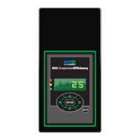
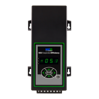
Describes controller indicator lights and button functions for navigation.

Controller Menus and Parameters

Lists available menus: Variables, Alarms, Setpoints, and Manual Control.

Controller Setup and User Interface

User Interface Navigation

Explains the 6-button interface for navigating controller menus.

Initial Controller Setup

Guide to configuring essential setpoints like Room Temp and Defrost Type.

Adjusting Controller Parameters

Information on accessing and adjusting controller parameters with passwords.

Controller Menu Parameters Reference

Manual Menu Parameters

Details parameters for manual control of the system components.

Variables Menu Parameters

Lists non-adjustable variables for sensor readings and system status.

Alarms Status Menu

Describes various alarm conditions and their descriptions.

Controller Setpoints Configuration

Setpoint Definitions (STPT)

Defines key setpoints for temperature, defrost, and valve control.

Setpoint Definitions (Bonded Controllers)

Details setpoints specific to multi-controller systems.

Controller Setpoints Details

Setpoint Range and Default Values

Provides ranges and default values for various controller setpoints.

Setpoint Configuration Options

Lists options for defrost types, valve types, and fan modes.

Related product manuals