Q.1.3 September 2012
Page 6
KE2 EvaporatorEfciency
Quick Start Guide
© Copyright 2012 KE2 Therm Solutions, Inc., Washington, Missouri 63090
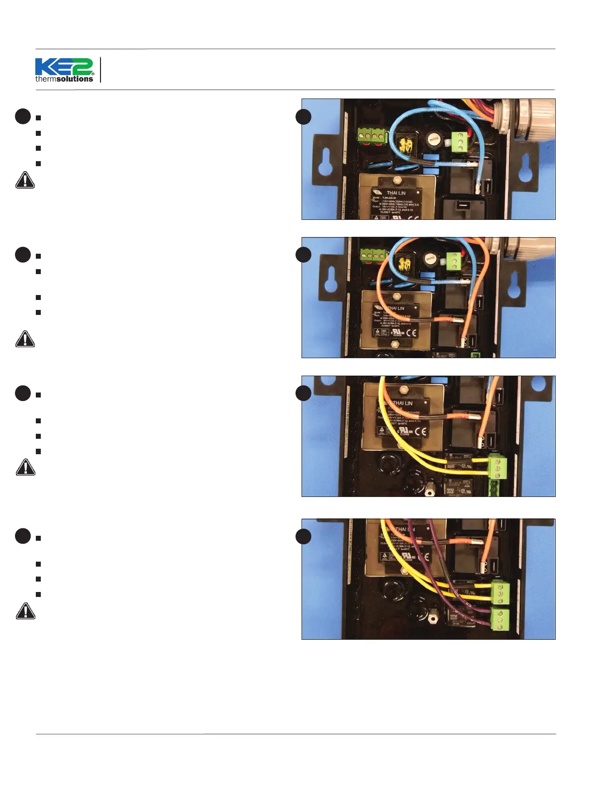
Fan Relay
Strip the end of the 2 wires used for fan control.
Locate 2 female spade connectors in the accessories kit.
Crimp on the female spade connectors.
Plug the connectors to the COM and NO positions of the Fan Relay.
Conrm combined fan motor load is not over 10 amps
8
8
Defrost (Heater) Relay
Strip the end of the 2 wires used for the defrost control.
Locate the remaining 2 female spade connectors in the accessories
kit.
Crimp on the female connectors.
Plug the connectors to the COM and NO positions of the Defrost
Relay.
Conrm combined heater load is not over 20 amps.
9 9
Liquid line solenoid /Compressor Relay
Strip approximately 1/4” of wire insulation on the end of the 2 wires
the will be used for the liquid line solenoid
Locate a 3 position connector from the accessories kit.
Fasten the wires to the screw terminals.
Plug into the location as indicated in Wiring Schematic.
Max relay rating is 3A
10 10
Auxiliary Relay
Strip approximately 1/4” of wire insulation on the end of the 2 wires
to be used for the alarm
Locate a 3 position connector from the accessories kit.
Fasten the wires to the screw terminals.
Plug into the location as indicated in Wiring Schematic.
Max relay rating is 3A
11
11
 Loading...