Q.1.3 September 2012
Page 5
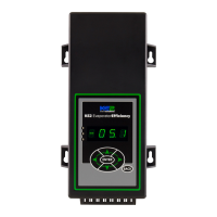
KE2 EvaporatorEfciency
Quick Start Guide
© Copyright 2012 KE2 Therm Solutions, Inc., Washington, Missouri 63090
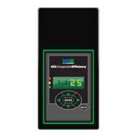
Determine the current draw of the unit.
Using the nameplate to determine the Amp rating of the unit. This
information should be used to select the proper sized wire. It should
also be used to verify the unit does not exceed the relay rating on the
KE2 Evaporator Eciency controller.
4 4
Preparing conduit
Feed the wires through the conduit.
The conduit connectors can be added at this time. Determine if a
straight or 90 degree connector is most appropriate for the installa-
tion, and attach to the conduit.
Securely connect one end of the conduit to the controller.
5 5
120V 208-240V
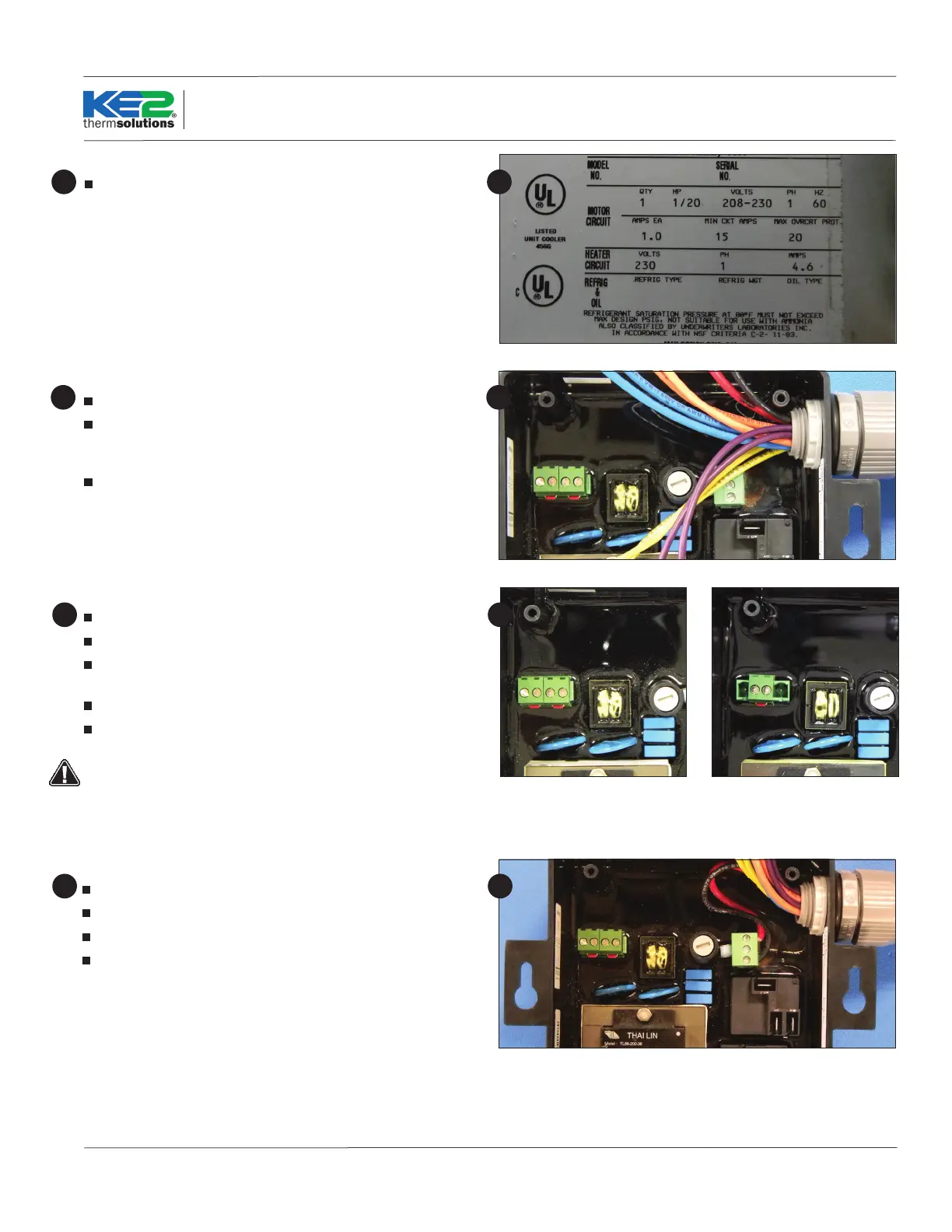
Wiring the controller
Locate the second Voltage Jumper in the accessory kit.
It is a 2 position plug with red jumper already installed.
Plug 1 jumper on the center 2 pins for 208-240V power and 2 jump-
ers on the outer 2 pins for 120V power.
Power is not connected to Voltage selector, it is a selector only.
Power for the controller is connected to the Power In location us-
ing a 3 position connector.
The controller will still illuminate the display when 120V is ap-
plied with 208-240V selected, however the controller will not
function properly.
6 6
Controller Power
Strip the end of the wires used to provide power to the controller
Locate a 3 position terminal in the accessories kit.
Fasten to the 3 position pluggable connector*.
Plug into the board as indicated in Wiring Schematic.
*All terminal screws should be tightened to 5 ft-lbs.
77
 Loading...