Do you have a question about the KE2 Therm Solutions 20844 and is the answer not in the manual?
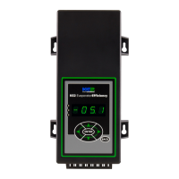
Lists all components included in the KE2 Evaporator Efficiency controller kit.
Lists standard truck stock items needed for installation.
Lists optional accessories available for separate purchase.
Provides a list of YouTube videos for installation and setup guidance.
Assess system health via superheat, subcooling, and temperature difference.
Explains frost formation and its effect on evaporator efficiency.
Discusses controller location based on user preference and accessibility.
Steps for cutting conduit, wires, and determining current draw.
Details on connecting power and selecting voltage for the controller.
Explains wire colors used in the KE2 Wire Harness for identification.
Instructions for wiring the Fan Relay and Defrost Relay.
Instructions for wiring the LLS/Compressor Relay.
Wiring the auxiliary relay and installing the safety cover.
Preparing the evaporator for wiring by turning off power.
Steps to study and understand the existing evaporator wiring.
Wiring the controller power input and evaporator fan connections.
Connecting evaporator heater wires to the terminal board.
Wiring defrost termination safety and LLS/Compressor.
Overview of wiring schematic using a KE2 Contactor Box.
Information on contactor ratings and fan/heater capacities.
Guidance on finding the best location for the coil sensor during defrost.
Checking that all heating elements are working properly.
Methods for installing the coil sensor, including protective plugs.
Wiring auxiliary components and labeling sensors for clarity.
Installing air temperature and coil sensors in their proper locations.
Connecting sensor wires to the controller and using strain relief.
Securing the controller and completing the installation.
Covers input voltage, temperature ranges, IP rating, inputs, and relays.
Details functions of digital inputs and communication protocols.
Identifies key components and connections on the back of the controller.
Explains how to move through controller menus and change settings.
Overview of Variables, Alarms, Setpoints, and Password menus.
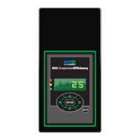
Explains the 6-button interface for navigation and input.
Guides through initial Room Temp, Defrost Type, Valve Type, and Smart Access setup.
Details password requirements for accessing controller setpoints.
Lists advantages and network connection requirements for Smart Access.
Steps to enable KE2 Smart Access in the Introduction Mode menu.
Instructions for logging into the KE2 Smart Access web portal.
Explains parameters like Room Temp, Defrost Type, Valve Type, and Superheat.
Lists available alarms and sensor readings for system monitoring.
Covers ranges for temperature setpoints, defrost times, and run times.
Details parameters for digital inputs, fan speed, and defrost modes.
Manual override options for control, relays, and factory reset.
Displays current system mode, sensor readings, and alarm meanings.
| Brand | KE2 Therm Solutions |
|---|---|
| Model | 20844 |
| Category | Controller |
| Language | English |