BL/BK
OR/BK
Y/BK
FAN/S
HEATERS
LL SOLENOID/COMP RELAY
BK/OR
L1
WT/R
L2
HS
GND
P/N 20996
12 AMP
20 AMP
3 AMP
OR NEUTRAL
HEATERS
thermsolutions
®
R/W
BL/BK
BK
BL/BK
FROM
CONTROLLER
EC MOTOR
RELAY
NO NC
COM
NO NC
COM
COM
NC
NO
COM
NC
N0
Solenoid Relay
Defrost
Relay
Fan
Relay
Power Input
Voltage Jumper
208-240 Default
L1
Ground
L2
COM
Auxiliary Relay
Supply Voltage
BL/BK
OR/BK
Y/BK
FAN/S
HEATERS
LL SOLENOID/COMP RELAY
BK/OR
L1
WT/R
L2
HS
GND
P/N 20996
12 AMP
20 AMP
3 AMP
OR NEUTRAL
HEATERS
thermsolutions
®
NO NC
COM
NO NC
COM
COM
NC
NO
COM
NC
N0
Solenoid Relay
Defrost
Relay
Fan
Relay
208-240
Power Input
Voltage Jumper
208-240 Default
L1
Ground
L2
COM
NC
NO
COM
NC
N0
Auxiliary Relay
FAN
MOTOR
FAN
MOTOR
FAN
MOTOR
EVAPORATOR
FANS
R/W
BL/BK
BK
BL/BK
FROM
CONTROLLER
EC MOTOR
RELAY
Q.1.3 November 2017
Page 6
KE2 EvaporatorEfciency
Quick Start Guide
© Copyright 2017 KE2 Therm Solutions, Inc., Washington, Missouri 63090
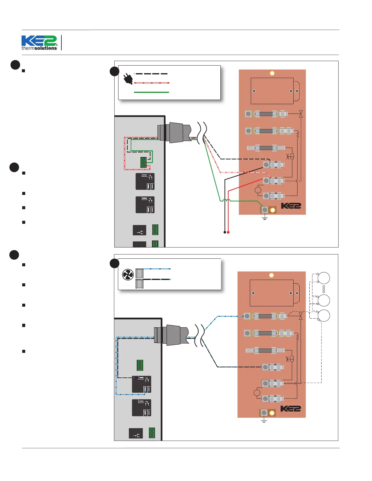
Study the existing wiring.
Although the existing terminal board
in the evaporator may be used, it is often
poorly labeled and dicult to wire. KE2
Therm provides a fused terminal board
(Item G in the parts list) that greatly sim-
plies wiring as well as provides addition-
al protection for controller components.
The instructions below are based on the
use of this board.
Determine the location of the following:
incoming power, fan leads, heater leads,
defrost termination leads, and fan delay
leads.
15
Evaporator wiring – Controller
Bring uninterrupted power to L1 and L2/
neutral on the terminal board. Connect
ground to the terminal board.
Strip the end of the wires used to power
the controller.
Attach to the line power to provide con-
tinuous power to the controller.
Connect ground from terminal board to
the controller
Note: Ground is required for the internal
safeties to operate properly.
16
Evaporator wiring – Fans
Strip the ends of the wires (connected
to the KE2 Evap) used to control the
evaporator fans.
The fan wires can be attached to the
terminal block using either screw down
terminals or spade connectors.
Attach one of the wires to the L1/Line.
This wire should be connected to COM of
fan relay on the controller.
Attach the wire connected to the NO
terminal on the Fan Relay to one of the
Fan Terminals on the supplied terminal
board.
Connect the remaining fan lead(s) to
the L2/Neutral position(s) on the termi-
nal board.
17
Black with white (L1)
16 AWG stripped and retained
White with red (L2/neutral)
16 AWG stripped and retained
Green (Ground)
16 AWG stripped and retained
Blue with black stripe
12 AWG ag connectors
Black with blue stripe (L1)
12 AWG ag connectors
17
16
 Loading...