Q.1.3 November 2017
Page 5
KE2 EvaporatorEfciency
Quick Start Guide
© Copyright 2017 KE2 Therm Solutions, Inc., Washington, Missouri 63090
Note: Before installing the safety cover, plug in any remaining connectors to
store for future use.
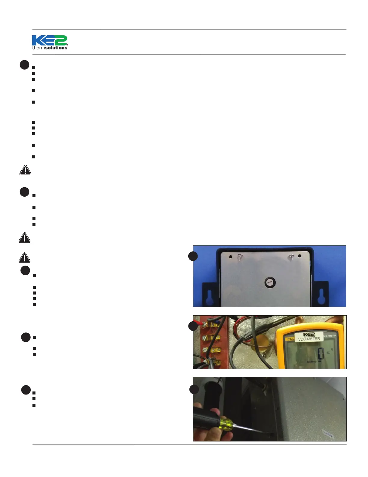
Install Safety cover
Once all of the high voltage wiring is complete, install the metal cover on
the controller.
Locate the cover and 3 small screws from the accessories kit.
Position the cover over the 3 mounting posts.
Using the 2 coarse thread screws attach cover to the plastic posts.
Use the ne threaded machine screw with lock washer to fasten the cover
to the metal post.
Set the controller in a safe place.
12
12
Preparing the Evaporator
The evaporator wiring will require access to the high voltage terminal block
on the coil.
Turn o power to the system.
Verify power is no longer present using a multimeter.
13
13
14
Evaporator wiring
Now that the conduit is prepared, it can be connected to the evaporator.
Locate the proper sized knockout and carefully remove knockout.
Connect conduit to the evaporator
14
Liquid Line Solenoid (LLS)/Comp. Relay USING KE2 Wire Harness
The YELLOW wires are used for LIQUID LINE SOLENOID control.
Locate a 3-position pluggable connector from the parts kit.
Fasten the black wire with yellow stripe into the COM position of the LLS/
Comp Relay.
Fasten the yellow wire with black stripe into the NO position of the LLS/
Comp Relay.
Plug the 3-position pluggable connector into the location as indicated in
the Wiring Schematic.
Liquid /Compressor Relay WITHOUT the KE2 Wire Harness
Strip the end of the 2 wires used to control the Liquid Line Solenoid.
Locate a 3-position pluggable connector from the parts kit.
Fasten the incoming power for the liquid line solenoid to COM position of
the LLS/Comp Relay
Fasten the lead from the liquid line solenoid to the NO position of the LLS/
Comp Relay.
Plug the 3-position pluggable connector into the location as indicated in
Wiring Schematic.
Max relay rating is 3A.
10
Auxiliary Relay
If using the Auxiliary Relay, the installer will need to supply an additional
pair of wires to the controller.
Strip approx. 1/4” of wire insulation on end of the 2 wires, for the auxiliary
device.
Locate a 3-position pluggable connector from the parts kit.
Plug the 3-position pluggable connector into the location as indicated in
the Wiring Schematic.
Max relay rating is 3A.
11
 Loading...