© Copyright 2021 KE2 Therm Solutions, Inc., Washington, Missouri 63090
Q.3.20 (Q.1.20) May 2021
thermsolutions
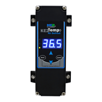
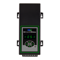
KE2 Temp + Air Defrost (pn 20611)
For Medium Temperature Applications with Air Defrost
Installation Manual
This reference should remain on site with the
installed KE2 Temp + Air Defrost controller.
Programming
Press & hold ENTER button
to access setpoint menu
Use arrow buttons to
select function:
tS = Temperature Setpoint
diF =
CSH = Max Compressor
Starts/ Hour
dPd = Defrost Per Day
dFt = Defrost Time
LAO =
tAd = Temp Alarm Delay
Adr = Mod Bus Address
Unt = Units for temp display
Press ENTER & use arrows
to change value
Press & hold ENTER button
Alarms
When amber LED is lit:
SSA = Shorted Sensor Alarm
OSA = Open Sensor Alarm
HtA = High Temp Alarm
LtA = Low Temp Alarm
pn 20679 06/14
B
C D
E
F
A
G
Parts List
The following parts are included in the KE2 Temp + Defrost kit:
(1) KE2 Temp + Defrost controller
(1) temperature sensor - 45”
(4) self-tapping mounting screws
(1) liquid tight cord grip
(1) sensor ziptie
(1) programming sticker
(2) screws for high voltage shield
Supplies List
All of the accessories required for the controller to work are supplied,
however, standard truck stock items are required to install the controller.
A list is provided below:
conduit to go between the controller & evaporator
(2) conduit connectors (straight or elbow as required)
(4) high voltage wires matched to the load of the liquid line solenoid/
compressor and the controller.
wire labeling (numbers, colors, etc.)
additional wire ties
18 gauge twisted shielded pair (if extending sensor wires)
foam insulation (if running wires outside the space)
silicone (for sealing any box penetrations)
Cat5e cable (if setting up communications)
Select Mounting Location
The KE2 Temp is designed for a wide range of applications; therefore
there are many potential installation locations. Breaking down the
installation location by application provides the most helpful reference.
Application Locations
Under counter
Evaporator cabinet
Outside controlled space
Walk-in
Evaporator cabinet
Adjacent to entrance
Side-by-side Above door
Remote Monitoring, Control, Alarm Notications
The KE2 Temp includes RS-485 Modbus communications and can be
accessed remotely using the Alarms KE2 Edge Manager (KE2 EM). See
page 4 for additional details.
Service Call Saver - Post Defrost Indicator
To eliminate unnecessary service calls, the KE2 Temp + Defrost alerts
the user when it is coming out of a defrost cycle using the onboard
display. The display alternates between dEF and the actual temperature
measured by the air sensor. This continues until the temperature has
reached setpoint, or for the amount of time set by dFt (Defrost Time)
whichever is shorter.
Walk-in Under Counter
CommercialWine Cabinet
A
C
D
E
B
F
G