KE2 Temp + Air Defrost (pn 20611)
For Medium Temperature Applications with Air Defrost
Installation Manual
Q.3.20 (Q.1.20) May 2021
Page 8
KE2 Therm Solutions
12 Chamber Dr. . Washington, MO 63090
636-266-0140 . www.ke2therm.com
© Copyright 2021 KE2 Therm Solutions, Washington, Missouri 63090
Q.3.20 (Q.1.20) May 2021 supersedes Q.3.20 (Q.1.20) December 2020 and all prior publications
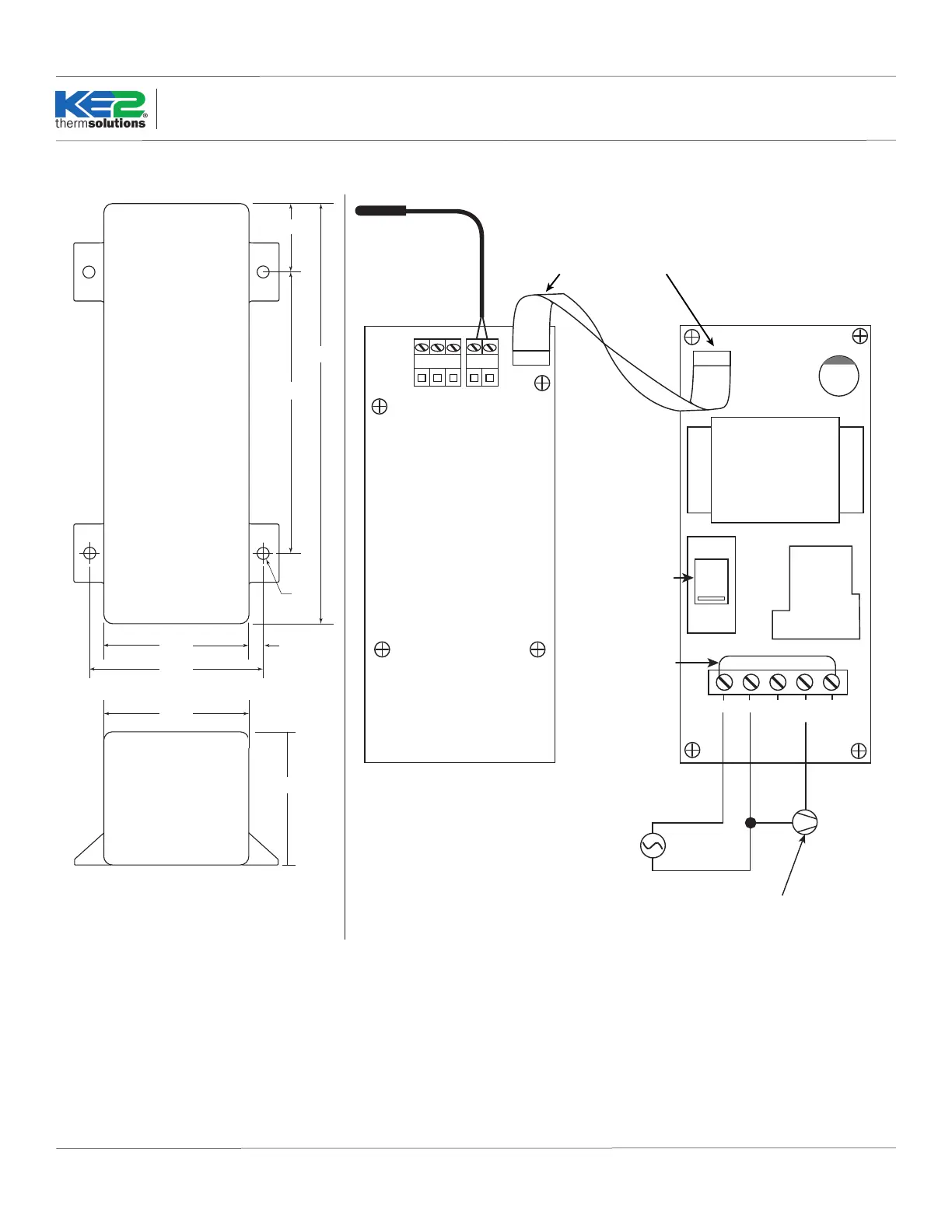
4.50
6.68
2.30
2.79
0.20
Hole
1.09
Top View
End View
2.14
2.30
Dimensions - Inches Wiring Diagram
Ribbon
Cable
Air Temp Sensor
120 (208 - 240)/1/60
CONTROLLER POWER SUPPLY
Neutral (L2)
NC
115/230
VAC
A B SH
RS 485
+ -
PWR CB
2 3 4 51
COM
NO
Relay
Put jumper
wire from
L1(terminal 1)
to COM
(terminal 5)
Observe proper orientation
of Ribbon Cable connection.
LLS (Liquid Line Solenoid) or
COMPRESSOR CONTACTOR
L1
Temp 1
Select correct
voltage for
controller power:
115 or 230V
 Loading...