Q.3.20 (Q.1.20) May 2021
Page 5
© Copyright 2021 KE2 Therm Solutions, Inc., Washington, Missouri 63090
KE2 Temp + Air Defrost (pn 20611)
For Medium Temperature Applications with Air Defrost
Installation Manual
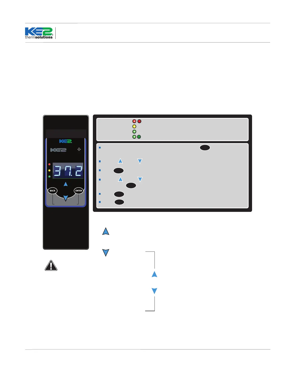
Programming the Controller
Access Setpoint mode by pressing and holding the button until
tS (temperature setpoint) displays on the screen
ENTER
Use the up and down arrows to scroll through the available setpoints.
ENTER
Press to view the current setting.
Indicator lights
Red blinking - the Real Time Clock battery needs replaced
Yellow light - non-critical alarm (system running)
Green light - compressor on
Green blinking - compressor waiting on timer to start/stop
tS = Temperature Setpoint
diF = Dierential
CSH = Maximum Compressor Starts/Hour
dPd = Defrost Per Day
tOd
d1
d2
d3
d4
d5
d6
d7
d8
d9
d10
d11
d12
dFt = Defrost Time
HAO = High Alarm Oset
LAO = Low Alarm Oset
tAd = Temp Alarm Delay
Adr = Mod Bus Address
Unt = Units for temp display (FAH or CEL)
Setpoints
Use the up and to change the setpoint
ENTER
Press to move between the digits to accelerate the changes.
ENTER
Press and hold to conrm each setpoint change
BACK
Press to escape.
Only visible if CUS (custom) is
selected for dPd (Defrost per day)
See page 7 for detailed setup
instructions.
Alarms
When amber LED is lit:
SSA = Shorted Sensor Alarm
OSA = Open Sensor Alarm
HtA = High Temp Alarm
LtA = Low Temp Alarm
Hold for manual defrost
thermsolutions
Temp
Air Defrost
Many applications of the KE2 Temp + Air Defrost can use the
controller’s preset defrosts per day. This automatically spaces the
defrosts throughout the day, based on the number of defrost cycles
selected. The user has the ability to change the number of defrost
cycles performed by changing the Defrost per Day setpoint from 0
to 12.
For more specic applications, the KE2 Temp has the option to
schedule each individual defrost at a specic time of day.
KE2 Temp + Air Defrost Basic Navigation
Understanding the KE2 Temp + Air Defrost’s menu structure will
simplify conguration. Figure 1 shows the basic button functions, as
well as a list of basic setpoints.
Low Battery Indicator
Blinking red light indicates the Real Time Clock battery needs to be
replaced.
Figure 1
 Loading...