© Copyright 2012 KE2 Therm Solutions, Inc., Washington, Missouri 63090
Q.1.3 September 2012
Page 4
KE2 EvaporatorEfciency
Quick Start Guide
KE2 EvaporatorEfficiency
TM
thermsolutions
ENTER
BACK
2
2
KE2 EvaporatorEfficiency
TM
thermsolutions
ENTER
BACK
2
2
KE2 EvaporatorEfficiency
TM
thermsolutions
ENTER
BACK
2
2
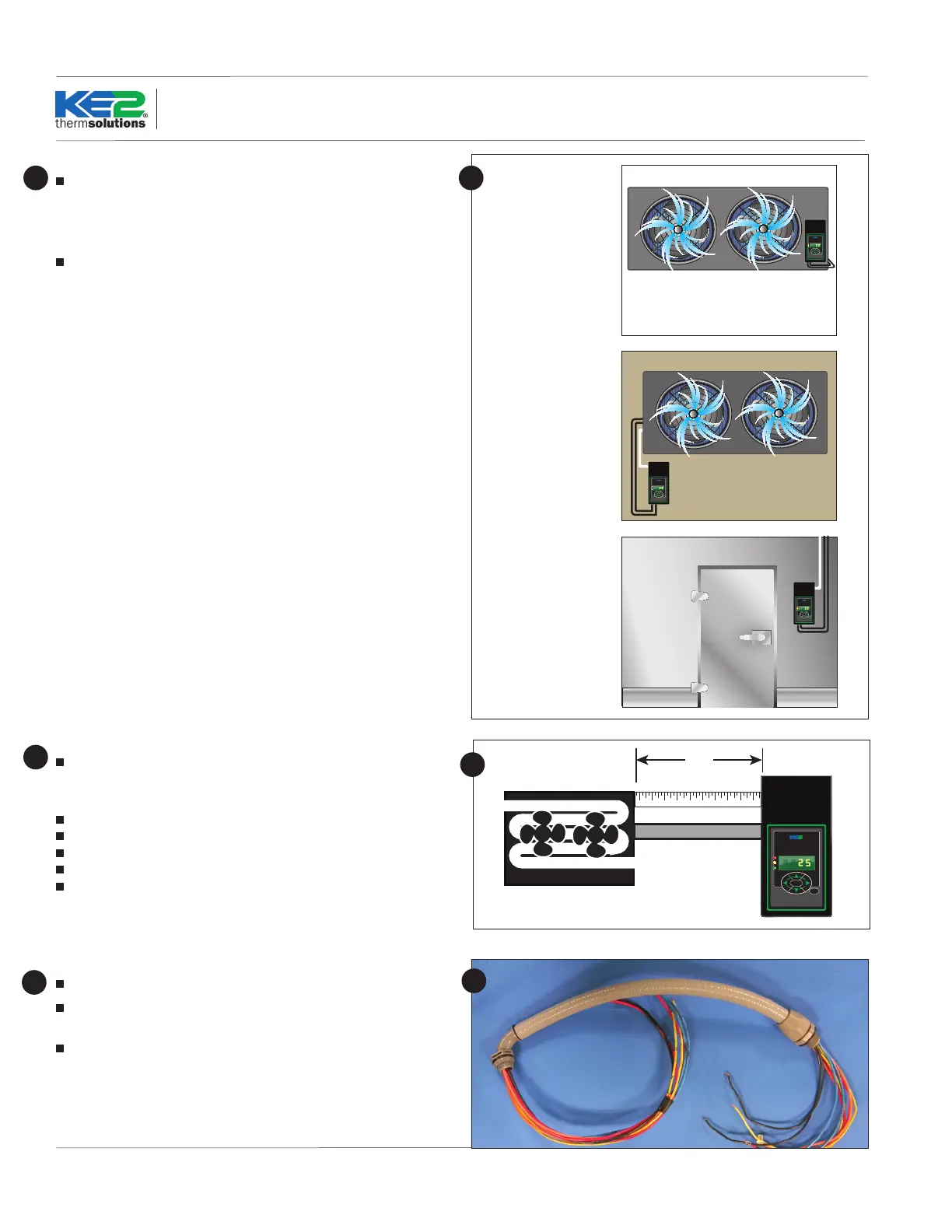
At the entrance
On the wall
On the evaporator
11
Determining Location
The controller is designed to be as versatile as possible. The loca-
tion should be discussed with the end users to determine if they have
a preference. It is designed so it can be installed inside or outside the
controlled space.
The controller can also be located at the condenser, but should not
be installed outdoors without an enclosure to protect it from sun-
light and moisture (must be within operating range -40°F to 140°F)
KE2 EvaporatorEfficiency
TM
thermsolutions
ENTER
BACK
2
2
Evaporator
Cut a length of conduit to go from the controller to the evaporator
Measure the distance between the controller and evaporator to ac-
count for the extra length necessary to properly route conduit.
Determine the number of wires to go to the controller.
Controller power (3 wires)
Fan control (2 wires)
Defrost (heater) control (2 wires)
Liquid line solenoid (2 wires)
Alarm relay (2 wires)
Note: Install in accordance with local wiring codes. KE2 Therm
does not accept responsibility for incorrect or unsafe wiring.
2
2
Cut wires to length
Once the number of wire is determined, cut the wires to length.
The wire should be long enough to account for the necessary con-
nections in the controller and evaporator.
Using dierent colored wires, (blue - fan, orange - heaters, yellow
- solenoid, purple - alarm) will simplify the installation and trouble-
shooting. If only a single color is available, both ends of the wires
should be labeled with a matching number. This will save time when
wiring the evaporator.
3
3
 Loading...