© Copyright 2017 KE2 Therm Solutions, Inc., Washington, Missouri 63090 © Copyright 2017 KE2 Therm Solutions, Inc., Washington, Missouri 63090
KE2 LowTemp
Quick Start Guide
KE2 LowTemp
Quick Start Guide
Subcooling - There should be a solid column of liquid at the inlet of the
valve. This can be veried by looking at the sight glass, however, the
proper method requires measuring the subcooling of the liquid enter-
ing the valve.
Verify Temperature Dierence
A typical Temperature Dierence (TD) between the coil temperature
and the air temperature is between 5 and 15°F. An insucient TD, be-
tween the coil and air temperature, indicates a system issue that needs
to be addressed before installing the KE2 Low Temp.
Understanding Frost
The air exiting side of the evaporator is often the coldest spot on
the coil. As air travels through the ns of the evaporator, the Relative
Humidity will reach 100%. Moisture will begin to drop out of the air and
deposit on the coil surfaces to form frost.
Mechanical timeclocks are commonly used to turn on defrost heaters
to remove the frost. While relatively eective, durability of the mecha-
nism is questionable and additional components, such as defrost ter-
mination sensors and fan delay relays, are also required. The KE2 Low
Temp performs the time based defrost function while including the
defrost termination, drip time, and fan delay functions in a robust elec-
tronic design. Additional features include heater cycling, and variable
fan modes to save energy, and door switch terminals, additional sen-
sors, and built-in communication abilities.
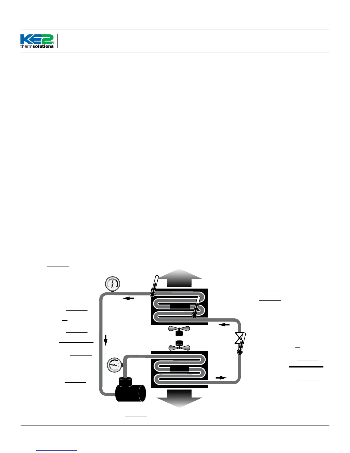
Liquid/Vapor Mix
Restrictor,
TEV or EEV
Warm Liquid
Cold Vapor
Hot Vapor
Warm Air
Cold Air
Evaporator
Compressor
Condenser
Saturation Temp °F
(from receiver pressure)
Liquid Temp at Valve °F
Subcooling °
Suction Pressure
PSI
Suction Temp °F
(evaporator outlet)
Saturation Temp °F
(calculated from Suct. Pressure)
Superheat °
Temp Dierence (TD)
°F
(return air minus coil temp)
Coldest point in evap °F
AMPS
Trouble Shooting Diagram
Discharge Pressure PSI
Refrigerant
Arriving at the Jobsite
When arriving at any jobsite, it is good practice to verify the correct op-
eration of the system. Even systems running for a considerable amount
of time without requiring a service call may not be running properly.
Inspect the coil to see the current frost pattern. If the unit has not re-
cently performed a defrost, look for the heaviest area of frost. This will
be used to locate the coil sensor.
Installers should account for a full system diagnostic in the installation
estimate for the controller.
Although it may seem unnecessary, identifying system issues before
the controller is installed will save time overall. It will also allow the
controller to provide the highest energy savings.
Verify the system is running correctly. Taking several measurements
will help determine the current health of the system. Using the diagram
below, ll in the necessary information.
Two of the most critical indicators of system health are the super-
heat and subcooling.
Superheat - Superheat is the most overlooked ineciency in existing
systems. Typically the superheat on a TEV is set when there is no prod-
uct in the controlled space, if it is set at all.
When applying the controller to an existing system with a mechanical
expansion valve, the superheat should be between 6-8 degrees for low
temperature applications and 8-10 degrees for medium temperature.
Q.3.29 (Q.1.29) May 2017
Page 2
 Loading...