© Copyright 2017 KE2 Therm Solutions, Inc., Washington, Missouri 63090 © Copyright 2017 KE2 Therm Solutions, Inc., Washington, Missouri 63090
KE2 LowTemp
Quick Start Guide
KE2 LowTemp
Quick Start Guide
Q.3.29 (Q.1.29) May 2017
Page 5
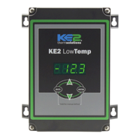
Determine the current draw of the unit.
Use the nameplate to determine the Amp rating of the unit. This
information should be used to select the proper sized wire. It should
also be used to verify the unit does not exceed the relay rating on the
KE2 Low Temp controller.
4 4
Preparing conduit
Feed the wires through the conduit.
The conduit connectors can be added at this time. Determine if a
straight or 90 degree connector is most appropriate for the installa-
tion, and attach to the conduit.
Securely connect one end of the conduit to the controller.
NOTE: If the controller is installed on the face of the evaporator, or
other location having access to the back of the controller, the upper
rear knockout will simplify conduit entrance. However, knockouts
are provided on the sides and bottom to allow the most convenient
wiring path. Power wiring should only pass through the side knock-
outs to maintain the safety of separation of high voltage and sensor
wiring. Sensor wiring may pass out the bottom or lower rear knock-
outs. No additional holes should be made in the eld.
5 5
115V 208-240V
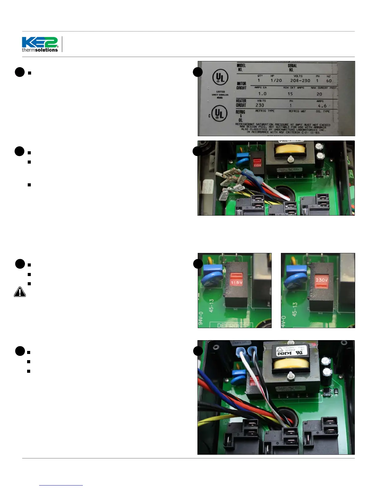
Wiring the controller
Locate the Voltage Selector Switch.
It is a 2 position switch with red indicator.
The selected voltage will be displayed on the face of the switch
The controller will still illuminate the display when 115V is ap-
plied with 208-240V selected, however the controller may not
function properly. If 208-240V is applied with 115V selected the
controller’s display will cycle rapidly.
6 6
Controller Power
Strip the end of the wires used to provide power to the controller
Crimp on female spade connectors (Item E from list on page 1)
Plug into the board as indicated in Wiring Schematic.
Note: All terminals should be crimped to withstand 30lb pull test.
77
 Loading...