EnDat at Channel 1
GB - 6
2.4 Mechanical installation
All kind of works on the inverter may be carried out by authorized personnel in accordance
with the EMC and safety rules only.
• Switch inverter de-energized and await capacitor discharge time
• Pullooperator
• Remove plastic cover
• Removexingbolt
• Fix interface board beginning from the socket connector straightly
• Screwinxingbolt
• Attach plastic cover
3. Description of the Interface
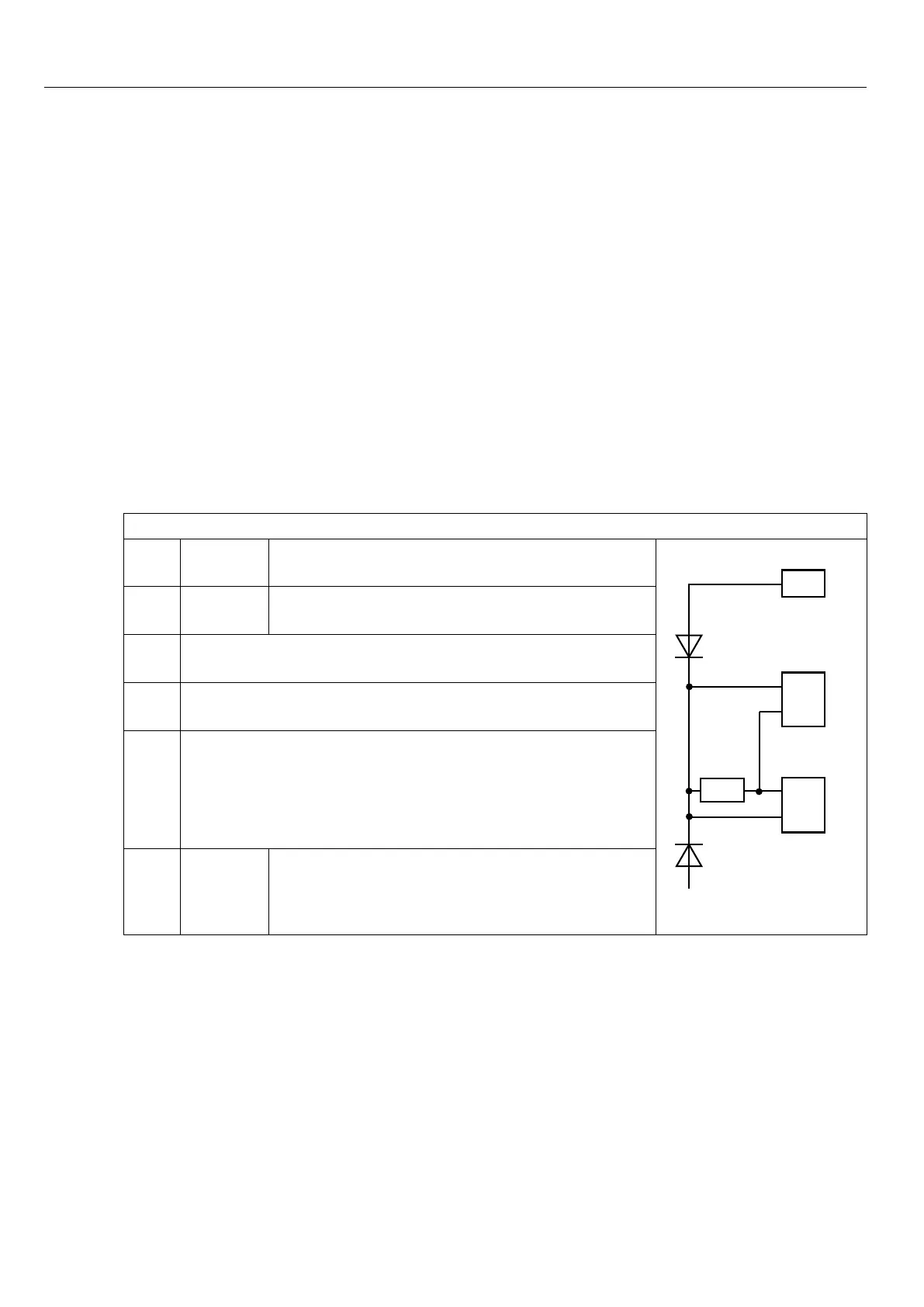
3.1 Voltage supply
Figure 3.1 Voltage supply of control and encoder interfaces
Uint 24 VDC Internal voltage supply of COMBIVERT.
X2A
X3A
X3B
5,2V
24V
5V
24V
5V
U
int
Uext
I
int
120 mA
at Hiperface, Sin/Cos, EnDat, SSI-Sin/Cos
and UVW.
Uext
Control terminal strip (X2A) of the COMBIVERT with
external voltage supply 24…30 DCV.
24 V
Voltage output of encoder interfaces X3A and X3B for
encoder supply.
I
24V
Current I
int
reduces itself by draw current at the 5 V-out-
put, as well as at the 7,5V-output in accordance with the
following formula:
5,2 V x I
5V
I
24V
= Iint
- –––––––––
U
int
I
5V
300 mA
at Hiperface, Sin/Cos, EnDat, SSI-Sin/Cos
and UVW.
3.2 Channel 2
The description of input X3B is depending on the used encoder interface. It is described in
a separate manual.
 Loading...