EnDat at Channel 1
GB - 8
3.3.3 Input signals channel 1
3.3.3.1 Process data channel
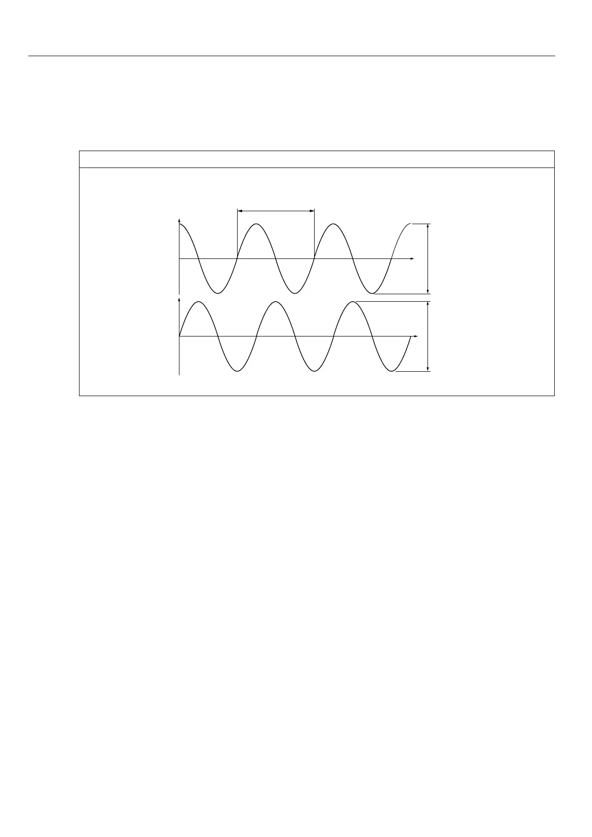
Figure3.3.3.1 SignalformAandBrespectivelytodierentialoperation
360°mechanical
Increments per revolution
A
B
0
0
typically 1 Vss
typically 1 Vss
3.3.3.2 Description of encoder signals
During start-up and then all 30 ms an inquiry is transmitted to the encoder and the absolute
position is serial read out. Thus a reference point search is not necessary.
As the increments per revolution are stored in the encoder, error Ec.37 = 70 is triggered
immediately, if a deviating value is entered in Ec.1.
Apositiondierenceistrackedafterlterwithramptime.Ifthisdierenceincreasestoquic-
kly, so that it cannot keep tracked or a max. value is exceeded (e.g.at encoder breakage),
theinterfacestateEc.37changesto„69“andtheinverterswitcheso.
The clock signal is used for synchronization.
3.3.3.3 Encoder breakage recognition
The recognition of encoder breakage is a software function and dependent on the encoder
type. Encoder breakage is noticeable only during encoder rotation.By writing on Ec.0 the
initialization starts. After fault-free initialization the correct position will be send.
The incremental track is monitored approx. all 16 ms. An error is triggered, if the permissi-
ble signal levels are fallen below. Also the absolute track, i.e. the serial communication to
the encoder is monitored. If the encoder gives not an answer, or a communication is not
possible, the respective state message will be transmitted to the inverter. Dependent on the
encoder type the response time can be 100 ms and more.
 Loading...