Card Connections and Installation
2-2
NOTE
All connecting wires or leads must be con-
nected to the card before it is installed in
the DMM.
2.3.1 Card configuration
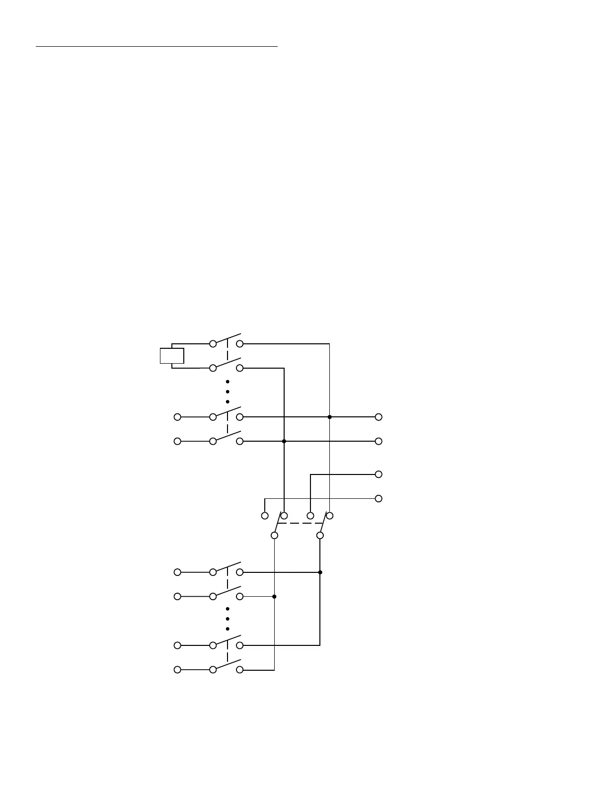
Figure 2-1 shows a simplified schematic diagram of the
Model 2001-TCSCAN. The scanner card has nine input
channels and two outputs. Channel 1 is the reference junc-
tion used for thermocouple temperature measurements.
4-pole paired channels are as follows:
• Channels 2 and 7
• Channels 3 and 8
• Channels 4 and 9
• Channels 5 and 10
CAUTION
Do not attempt to pair channels 1 and 6.
Possible damage to the reference junc-
tion may result if a signal is applied to
channel 6 if channels 1 and 6 are used
together in the 4-pole mode.
Channel 1
(Reference
Junction)
HI
LO
Channel 2-4
Channel 5
HI
LO
Channel 6
HI
LO
Channel 7-9
Channel 10
HI
LO
OUT A (To DMM
input jacks)
OUT B (To DMM
sense jacks)
HI
LO
2-Pole4-Pole
Figure 2-1
Model 2001-TCSCAN simplified schematic