Step
r
1
2
3
4
5
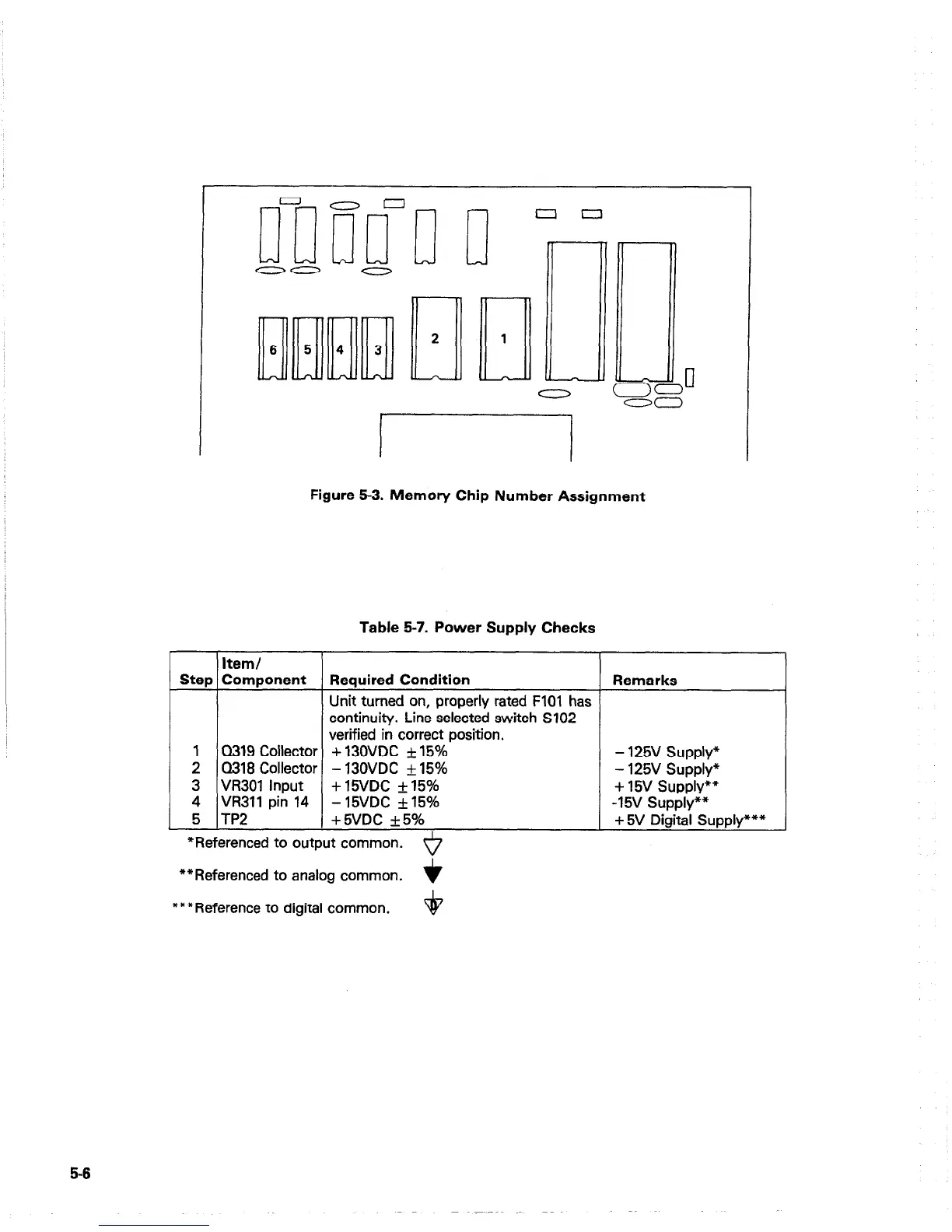
Figure 5-3. Memory Chip Number Assignment
Table 5-7. Power Supply Checks
Item/
Component
Required Condition
Remarks
Unit turned on, properly rated FlOl has
continuity. Line selected switch S102
verified in correct position.
0319 Collector + 130VDC f 15% - 125V Supply*
Q318 Collector - 130VDC f 15%
- 125V Supply”
VR301 Input + 15VDC &- 15%
+ 15v supply**
VR311 pin 14 - 15VDC &- 15%
-15v Supply””
TP2 +5VDC +5%
+ 5V Digital Supply***
*Referenced to output common.
*
**Referenced to analog common.
+
***Reference to digital common.
+
5-5