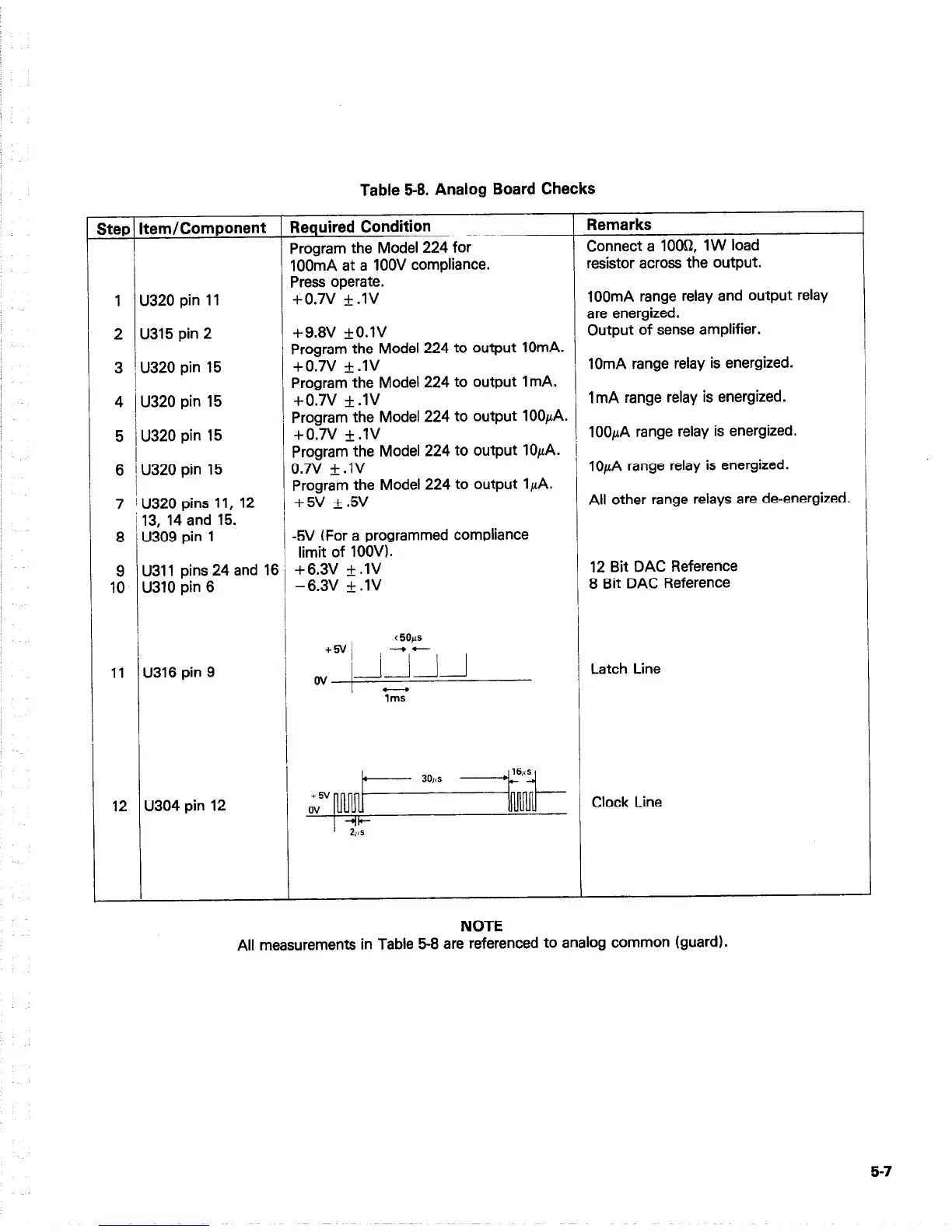
Table 58. Analog Board Checks
itep Item/Component
Required Condition
Remarks
Program the Model 224 for
Connect a 1 OOQ, 1 W load
IOOmA at a 1OOV compliance.
resistor across the output.
Press operate.
1 U320 pin 11
+O.N **IV
100mA range relay and output relay
are energized.
2 U315 pin 2
+9.8V +O.lV
Output of sense amplifier.
Program the Model 224 to output lOmA.
3 i u320 pin I5
+0.7v +.lV
10mA range relay is energized.
Program the Model 224 to output ImA.
4 / U320 pin 15
+0.7v +.lV
ImA range relay is energized.
Program the Model 224 to output 100p.A.
5 U320 pin 15
+O.N +.lV
lOOpA range relay is energized.
Program the Model 224 to output lOpA. i
6 I U320 pin 15
0.7v *.lV
lOpA range relay is energized.
7 jU320 pins 11, 12
Program the Model 224 to output IpA.
+5v +.5v
All other range relays are de-energized.
113, 14and 15.
8 / U309 pin 1
-5V (For a programmed compliance
limit of 1OOV).
9 U311 pins 24 and 16 +6.3V f .lV
12 Bit DAC Reference
10 U310 pin 6
-6.3V + .lV
8 Bit DAC Reference
11 U316 pin 9
Latch Line
12 U304 pin 12
16,~
.
30,as
+6V
ov
1
lumr
Clock Line
+I+
2,a
NOTE
All measurements in Table 5-8 are referenced to analog common (guard).
5-7