14-6 Calibration
Step 2: Perform Channel #1 (battery channel) calibration steps
NOTE The unit will display the most recently calibrated values. Factory defaults are shown
in this manual.
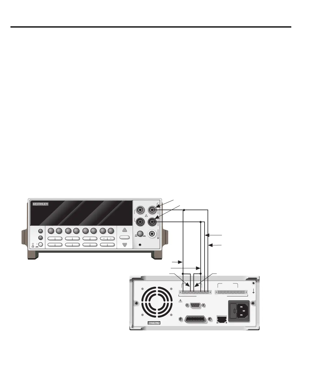
1. Connect the OUTPUT #1 SOURCE, SENSE, and
DVM IN terminals to the DMM, as
shown in Figure 14-1.
DMM Input connections:
HI: SOURCE +, SENSE +, and DVM IN +
LO: SOURCE -, SENSE -, and DVM IN -
2. At this point, the Model 2306 will prompt you to set the full-scale Channel #1 output
v
oltage:
CAL VOLTS CHAN 1
SET 14.0000 V
1. Use the edit keys to set the voltage to 14.0000V, then press ENTER.
NOTE At this point, the source output is turned on and will remain on until calibration is
comple
te or aborted with the MENU key.
Figure 14-1
Connections for voltage calibration
WARNING:NO INTERNAL OPERATOR SERVICABLE PARTS,SERVICE BY QUALIFIED PERSONNEL ONLY.
CAUTION:FOR CONTINUED PROTECTION AGAINST FIRE HAZARD,REPLACE FUSE WITH SAME TYPE AND RATING.
MADE IN
U.S.A.
LINE RATING
100-120VAC, 200-240VAC
50, 60 HZ 165VA MAX
LINE FUSE
SLOWBLOW
2.0A, 250V
IEEE-488
(ENTER IEEE ADDRESS
FROM FRONT PANEL MENU)
REMOTE
DISPLAY
OPTION
+++
____
+
SOURCE SENSE
DVM IN
SOURCE
OUTPUT #1
ISOLATION FROM EARTH: 22 VOLTS MAX.
RELAY
CONTROL
24VDC MAX
CAT I
DVM IN
+30 VDC MAX
NEXT
PREV
POWER
DISPLAY
2001 MULTIMETER
DCV ACV DCI ACI Ω2 Ω4
FREQ TEMP
REL TRIG
INFO LOCAL EXIT ENTER
RANGE
RANGE
!
FR
500V
PEAK
FRONT/REAR
2A 250V
AMPS
CAL
STORE RECALL
CHAN SCAN
FILTER MATH
CONFIG MENU
HI
INPUT
LO
SENSE
Ω 4 WIRE
INPUTS
350V
PEAK
1100V
PEAK
AUTO
Model 2001 DMM
Model 2306
Input LO
Input HI
Source +
Source -
DVM IN -
DVM IN +
OUTPUT #1 connections
shown. Use OUTPUT #2
for Charger Channel.
Sense +
Sense -
+++
____
+
SOURCE SENSE
DVM IN
SOURCE
OUTPUT #2
Test Equipment Depot - 800.517.8431 - 99 Washington Street Melrose, MA 02176
TestEquipmentDepot.com