E-6 Applications Guide
NOTE Figure E-5 contains the effect of the variable output impedance control of the
Model 2306 on the current and voltage performance of a GSM handset.
Two methods are used to determine the impedance value of the cell or battery pack. The first
method use
s data from the battery manufacturer or another source and is simply entered into the
Model 2306 from the front panel or over the GPIB bus. The second method involves a simple
series of measurements as follows.
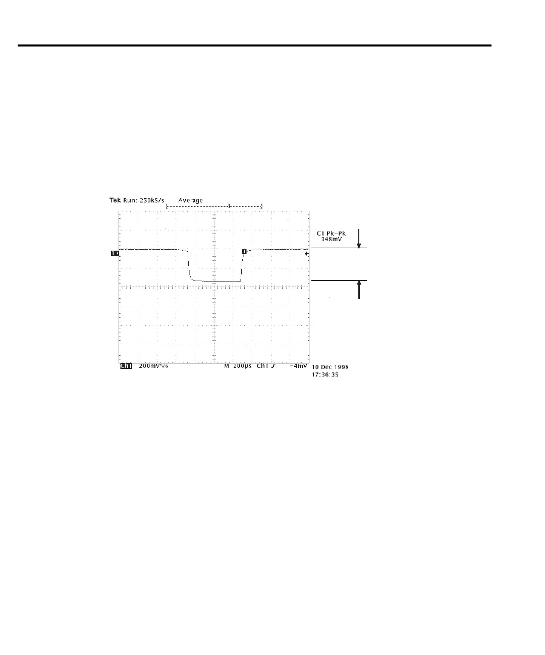
Figure E-6
Li ion voltage drop during the transmit portion of the pulse
V
H
– V
L
= 0.348 V
NOTE Figure E-6 shows the voltage drop during the transmit portion of the pulse of a GSM
phone with the supplied Li ion.
Figure E-6 sho
ws the transient voltage response at the battery terminals with the handset
battery. Using the pulse current mode of the battery channel, the measured
current during the
transmit portion of the data frame is I
H
= 1.536A and the idle portion of the data frame is
I
L
= 0.082A. To estimate R
i
from the measured voltage in Figure E-6, use:
R
i
V
H
V
L–
I
H
I
L
–
--------------------
0.348V
1.454A
-----------------
0.239
Ω
==≅
Test Equipment Depot - 800.517.8431 - 99 Washington Street Melrose, MA 02176
TestEquipmentDepot.com