2.28
MAKING STABLE MEASUREMENTS
Stability
Considerations (Single Source
Measure
Unit)
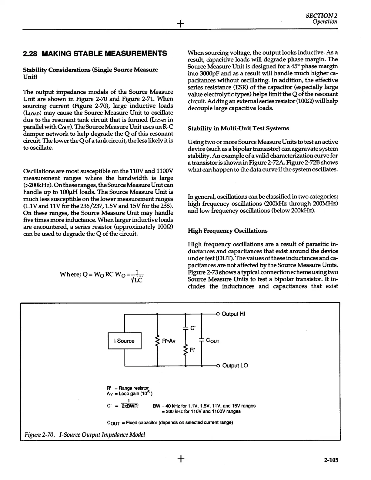
The
output
impedance models of the
Source
Measure
Unit are shown
in
Figure
2-70
and
Figure
2-71.
When
sourcing current (Figure
2-70), large inductive loads
(LwAo)
may cause the Source Measure
Unit
to oscillate
due
to the resonant tank circuit that is formed
(LwAo
in
parallel with
CoUT).
The
Source
Measure
Unit
uses
an
R-C
damper network to help degrade the
Q
of
this
resonant
circuit. The lower the
Q
of a tank circuit, the less likely it is
to oscillate.
Oscillations are most susceptible
on
the
110V
and
1100V
measurement ranges where the bandwidth is large
(>200kHz).
On
these ranges, the Source Measure
Unit can
handle
up
to
100J.IH
loads. The Source Measure Unit
is
much less susceptible
on
the lower measurement ranges
(1.1V
and
llV
for the 236/237,
l.SV
and
15V
for the
238).
On
these ranges, the
Source
Measure
Unit
may
handle
five times more inductance. When larger inductive loads
are encountered, a series resistor (approximately
1000)
can be used to degrade the
Q
of the circuit.
Where;
Q=WoRCWo=-1-
YLC
+
SECTION2
Operation
When sourcing voltage, the
output
looks inductive. As a
result, capacitive loads will degrade phase margin. The
Source Measure
Unit
is designed for a
45°
phase margin
into
3000pF
and
as a result will handle much higher ca-
pacitances without oscillating.
In
addition, the effective
series resistance
(ESR)
of the capacitor (especially large
value electrolytic types) helps limit the
Q
of the resonant
circuit. Adding
an
external series resistor
(lOOn)
will help
decouple large capacitive loads.
Stability
in
Multi-Unit
Test
Systems
Using
two
or
more Source Measure Units to test
an
active
device (such as a bipolar transistor) can aggravate system
stability.
An
example of a valid characterization curve for
a transistor is
shown
in Figure 2-72A. Figure
2-72B
shows
what
can
happen
to the
data
curve
if
the system oscillates.
In
general, oscillations can be classified
in
two categories;
high frequency oscillations
(200kHz
through
200MHz)
and
low frequency oscillations (below
200kHz).
High
Frequency Oscillations
High
frequency oscillations are a result of parasitic in-
ductances
and
capacitances that exist around the device
under
test (OUT). The values of these inductances
and
ca-
pacitances are not affected
by
the Source Measure Units.
Figure 2-73 shows a typical connection scheme using two
Source Measure
Units
to test a bipolar transistor.
It
in-
cludes the inductances
and
capacitances that exist
~------~------~--~--~~ou~utHI
be·
II
Source
I
L--------+------'"-__.---o
Output
LO
A' = Range resistor
Av
=Loop
gain (10
6
)
1
C' = 2ltBWR' BW = 40
kHz for 1.1V, 1.5V,
11
V,
and 15V ranges
=
200
kHz for
11
OV
and
11
OOV
ranges
CouT
=Fixed
capacitor (depends on
selected
current range)
Figure
2-70.
!-Source
Output
Impedance
Model
+
2-105
 Loading...


