Source
Measure
Unit#1
Output
LO
Ce1
300pF
+
System
Common
CE2
300pF
SECTION2
Operation
Source
Measure
Unit#2
Source
I
m =
Earth
Ground
Source
V
Measure
I
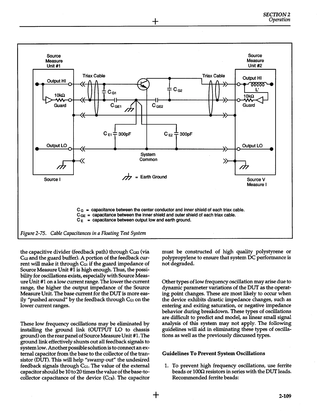
C
G
=
capacitance
between
the
center conductor
and
inner shield
of
each
triax
cable.
CGe
= capacitance
between
the inner
shield
and
outer
shield
of
each
triax
cable,
C e
= capacitance
between
output
low
and
earth
ground.
Figure
2-75.
Cable
Capacitances
in
a
Floating
Test
System
the capacitive divider (feedback path) through
CGE2
(via
CG2
and
the
guard
buffer). A portion of the feedback cur-
rent
will
make
it
through
CGI
if
the
guard
impedance of
Source Measure
Unit
#1
is high enough. Thus, the possi-
bility for oscillations exists, especially with Source Meas-
ure
Unit
#1
on
a low current range. The lower the current
range, the higher the
output
impedance of the Source
Measure
Unit. The base current for the OUT is more eas-
ily "pushed around"
by
the feedback through
CGt
on
the
lower current ranges.
These low frequency oscillations
may
be
eliminated
by
installing the
ground
link (OUTPUT
LO to chassis
ground)
on
the rear panel of Source Measure
Unit
#1.
The
ground link effectively shunts
out
all feedback signals to
system low. Another possible solution is to connect
an
ex-
ternal capacitor from the base to the collector of the tran-
sistor (OUT). This will help
"swamp
out"
the undesired
feedback signals through
CGt.
The value of the external
capacitor should
be
10 to
20
times the value of
the
base-to-
collector capacitance of the device
(Cca).
The capacitor
+
must
be
constructed of high quality polystyrene or
polypropylene to ensure
that
system DC performance is
not degraded.
Other types of low frequency oscillation
may
arise
due
to
dynamic parameter variations of the OUT as the operat-
ing
point changes. These are most likely to occur when
the device exhibits drastic impedance changes, such as
entering
and
exiting saturation,
or
negative impedance
behavior
during
breakdown. These types of oscillations
are difficult to predict
and
model, as linear small signal
analysis of this system
may
not apply. The following
guidelines
will
aid
in
eliminating these types of oscilla-
tions as well as the previously discussed types.
Guidelines
To
Prevent System Oscillations
1.
To prevent high frequency oscillations, use ferrite
beads
or
1000
resistors
in
series
with
the OUT leads.
Recommended ferrite beads:
2-109
 Loading...


