SECTION2
Operation
Source
Measure
Unit#1
Output
HI
+
System
Common
Source
Measure
Unit#2
Source
I
m =
Earth
Ground
Source
V
Measure
I
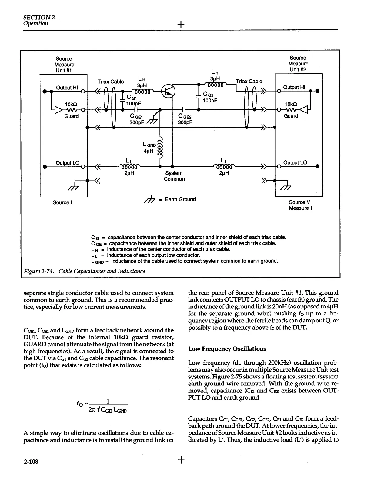
C
G
=
capacitance
between
the
center conductor
and
inner shield
of
each
triax
cable.
C
GE
=
capacitance
between
the
inner shield
and
outer
shield
of
each
triax
cable.
L
H
=
inductance of
the
center conductor
of
each
triax
cable.
L
L
=
inductance
of
each
output
low
conductor.
L
GND
=
inductance
of
the
cable
used
to connect
system
common
to
earth
ground.
Figure
2-74.
Cable
Capacitances
and
Inductance
separate single conductor cable
used
to connect system
common to earth ground. This is a recommended prac-
tice, especially for
low
current measurements.
CGEt,
CGE2
and
LGNo
form a feedback network
around
the
OUT. Because of
the
internal
10k.Q
guard
resistor,
GUARD cannot attenuate
the
signal from
the
network (at
high frequencies). As a result, the signal is connected to
the OUT via
CGt
and
CG2
cable capacitance. The resonant
point
(fo)
that
exists is calculated as follows:
fo-
1
21t
V
CGE
LGm
A simple
way
to eliminate oscillations
due
to cable ca-
pacitance
and
inductance is to install
the
ground
link
on
2-108
+
the
rear
panel
of
Source
Measure
Unit
#1. This
ground
link connects OUTPUT
LO
to chassis (earth) ground. The
inductance of
the
ground
link is 20nH (as opposed to
4~
for
the
separate
ground
wire)
pushing
fo
up
to a fre-
quency region
where
the ferrite
beads
can
damp
out
Q
or
possibly to a frequency above
&
of
the
OUT.
Low
Frequency
Oscillations
Low frequency (de
through
200kHz)
oscillation prob-
lems
may
also occur
in
multiple
Source
Measure
Unit
test
systems. Figure 2-75 shows a floating test system (system
earth
ground
wire removed. With
the
ground
wire re-
moved, capacitance
(CEt
and
CE2>
exists between
OUT-
PUT
LO
and
earth ground.
Capacitors
CGt,
CGEt,
CG2,
CGE2,
CEt
and
CE2
form a feed-
back
path
around
the
OUT.
At
lower frequencies,
the
im-
pedance
of
Source Measure
Unit
#2looks inductive as in-
dicated
by
L'. Thus, the inductive load (L') is applied to
 Loading...


