Source
Measure
Unit#1
Output
HI
Source
I
Cce
=collector-to-base
capacitance
Cee
=base-to-emitter capacitance
Cce
=
collector-to-emitter
capactance
L
c
=
collector
inductance
L
e = base
inductance
L
e
=
emitter
inductance
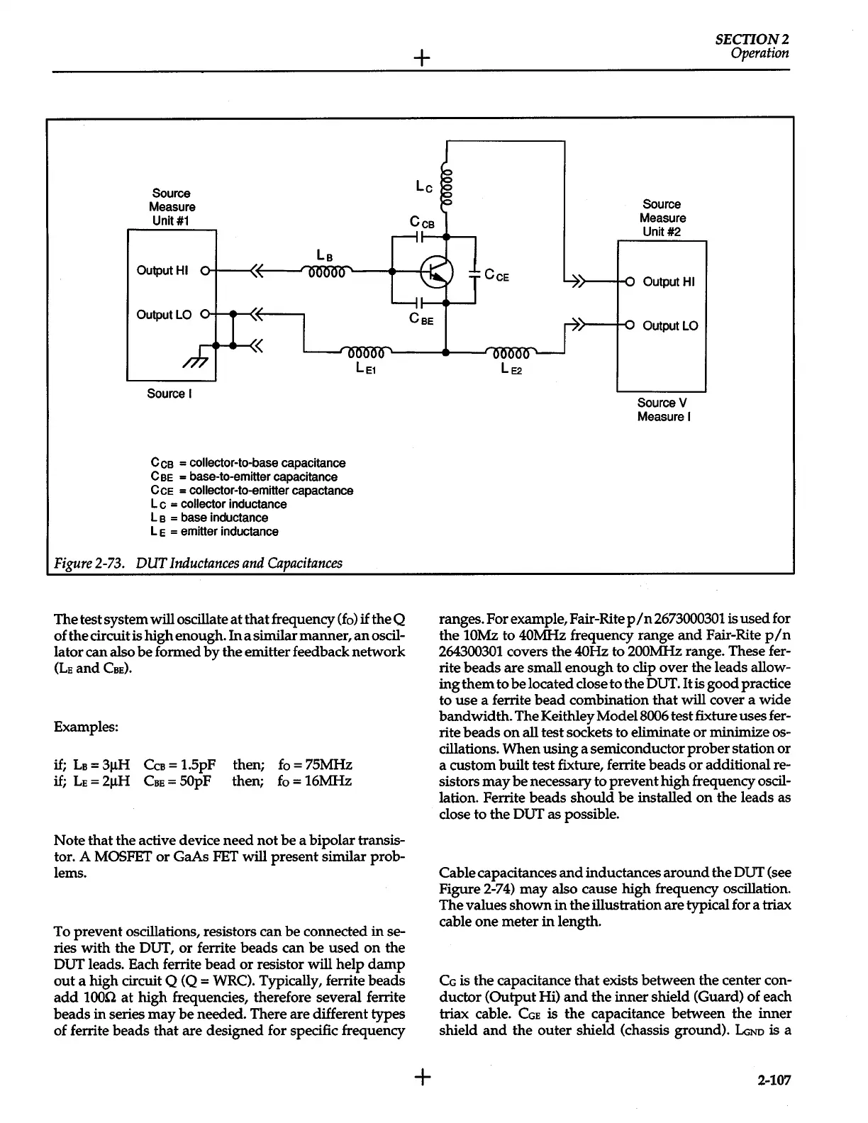
Figure
2-73.
DUT
Inductances
and
Capacitances
The test system will oscillate
at
that
frequency
(fo)
if
the
Q
of
the
circuit is
high
enough.
In
a similar
manner,
an
oscil-
lator
can
also
be
formed
by
the
emitter feedback
network
(LE
and
CBE).
Examples:
if;
LB
=
3j.lH
CcB
=
1.5pF
if;
LE
=
2j.lH
CBE
= 50pF
then;
fo
=
75MHz
then;
fo
=
16MHz
Note
that
the
active device
need
not
be
a
bipolar
transis-
tor.
A
MOSFET
or
GaAs PET will
present
similar prob-
lems.
To
prevent
oscillations, resistors
can
be
connected
in
se-
ries
with
the
OUT,
or
ferrite
beads
can
be
used
on
the
OUT leads. Each ferrite
bead
or
resistor will
help
damp
out
a
high
circuit
Q
(Q
= WRC). Typically, ferrite
beads
add
1000
at
high
frequencies, therefore several ferrite
beads
in
series
may
be
needed. There are different
types
of ferrite
beads
that
are
designed for specific frequency
+
+
LE2
Source
Measure
Unit#2
Output
HI
Output
LO
Source
V
Measure
I
SECTION2
Operation
ranges. For example, Fair-Rite
pIn
2673000301
is
used
for
the
10Mz
to
40MHz frequency
range
and
Fair-Rite
p/n
264300301
covers
the
40Hz
to
200MHz
range. These fer-
rite
beads
are
small
enough
to
clip
over
the
leads allow-
ingthem
to
be
located close
to
the
OUT.It
is
good
practice
to
use
a ferrite
bead
combination
that
will
cover a
wide
bandwidth.
The Keithley
Model8006
test fixture uses fer-
rite
beads
on
all
test
sockets
to
eliminate
or
minimize os-
cillations.
When
using
a semiconductor
prober
station
or
a
custom
built
test
fixture, ferrite
beads
or
additional re-
sistors
may
be
necessary
to
prevent
high
frequency oscil-
lation. Ferrite
beads
should
be
installed
on
the
leads as
close
to
the
OUT
as
possible.
Cable capacitances
and
inductances
around
the
OUT (see
Figure 2-74)
may
also cause
high
frequency oscillation.
The
values
shown
in
the
illustration
are
typical for a triax
cable
one
meter
in
length.
CG
is
the
capacitance
that
exists
between
the
center con-
ductor
(Output
Hi)
and
the
inner
shield (Guard) of each
triax cable.
CGE
is
the
capacitance
between
the
inner
shield
and
the
outer
shield (chassis ground).
LGNo
is a
2-107
 Loading...


