3.7.1
Factors
Affecting
Sweep
Times
Basically, there are four phases
to
programming
the
in-
strument, performing a sweep,
and
transmitting
data
over the bus:
1.
Programming phase: Here, all
the
necessary operat-
ing
modes are
programmed
by
sending appropriate
commands over
the
bus. Typically,
you
will
select
the
bias,
sweep
waveform type
and
parameters,
reading rate,
and
trigger configuration.
2.
Trigger phase: To perform a sweep,
the
unit
must
be
triggered
in
some
fashion;
that
trigger will,
of
course,
depend
on
the
programmed
trigger origin.
If
the
in-
strument
is to be synchronized
with
external equip-
ment,
an
external trigger origin
should
be
selected.
If
you
intend to trigger the
unit
from a controller,
use
one
of
the
IEEE
trigger origins
(X,
GET,
or
Talk). The
best
one
to
use
depends
on
when
you
want
the
sweep to occur. With a trigger
on
X,
the
sweep
starts
when
the
X character is received
with
the
trigger
configuration command. A trigger
on
Talk starts a
sweep
when
the
controller requests
the
output
data.
A trigger
on
GET can
start
a
sweep
any
time after the
trigger is configured
and
before the
data
is re-
quested. The trigger origins
with
the fastest response
times are External
and
IEEE GET ( <2msec).
3. Sweep phase: During this phase,
the
instrument cy-
cles through
the
steps
of
the
sweep
waveform
and
takes readings. The
number
of
readings is program-
mable.
4.
Data transmission phase:
Once
the
sweep
has com-
pleted
and
the
data
is stored
in
the
Model
236/237/238
sweep
buffer,
data
must
be
transmitted
to the computer. There are
two
methods
that
can
be
used: complete
sweep
data
transmission
and
single
line transmission.
If
your
computer can
handle
a
long string
of
bytes,
program
the
Model
236/237/238 to
dump
all lines
of
sweep
data.
3.7.2
Optimizing
Source
and
Measure-
ment
Speed
The length
of
a source-delay-measure cycle
depends
on
several factors,
among
them
are:
•
Source settling
time-
Response time to a source value
change to within a rated accuracy.
•
Source range changing times,
if
necessary.
•
Measurement settling time - Response time to a
measurement change to within a rated accuracy.
•
Measurement integration time - Interval between
analog to digital conversions.
•
Measure range changing times,
if
necessary.
+
+
SECTION3
IEEE-488
Reference
These factors become critical
at
low
current levels be-
cause
of
the
following:
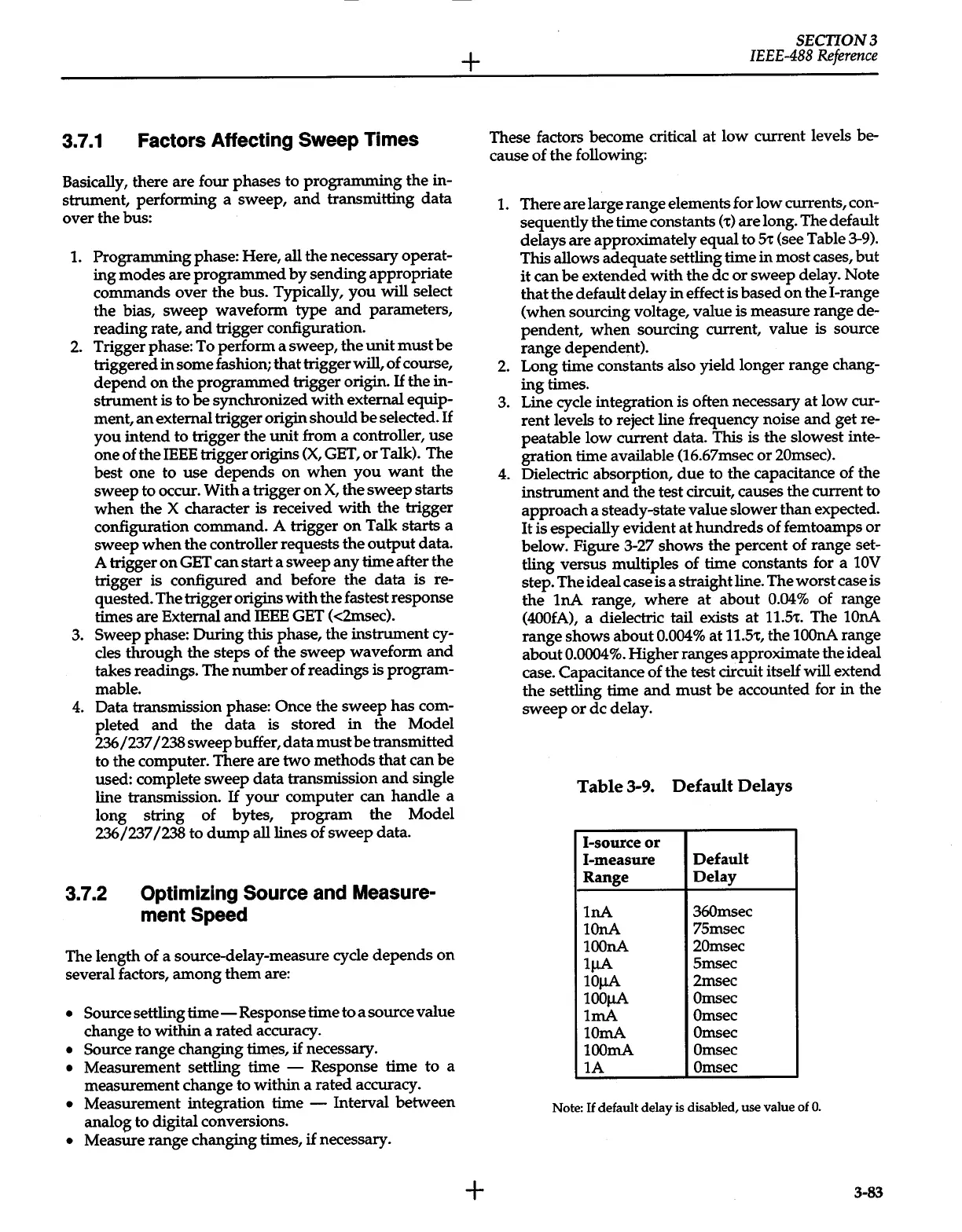
1.
There are large range elements for
low
currents, con-
sequently
the
time constants (
t)
are long. The default
delays are approximately equal to
5t
(see Table 3-9).
This allows adequate settling time
in
most cases,
but
it
can
be
extended
with
the
de
or
sweep delay. Note
that
the
default delay
in
effect is
based
on
the I-range
(when sourcing voltage, value is measure range de-
pendent,
when
sourcing current, value is source
range dependent).
2.
Long time constants also yield longer range chang-
ing
times.
3. Line cycle integration is often necessary
at
low cur-
rent levels to reject line frequency noise
and
get re-
peatable
low
current data. This is
the
slowest inte-
gration time available (16.67msec
or
20msec).
4.
Dielectric absorption,
due
to
the
capacitance of the
instrument
and
the
test circuit, causes
the
current to
approach a steady-state value slower
than
expected.
It
is especially evident
at
hundreds
of
femtoamps
or
below. Figure 3-27 shows the percent
of
range set-
tling versus multiples of time constants for a
lOV
step. The ideal case is a straight line. The
worst
case is
the
lnA
range,
where
at
about
0.04%
of range
(400fA),
a dielectric tail exists
at
ll.St.
The lOnA
range shows
about
0.004%
at
ll.St,
the
lOOnA
range
about
0.0004%.
Higher
ranges approximate the ideal
case. Capacitance
of
the
test circuit itself will extend
the
settling time
and
must
be
accounted for
in
the
sweep
or
de
delay.
Table
3-9.
Default
Delays
1-source
or
1-measure
Default
Range
Delay
lnA
360msec
lOnA
75msec
lOOnA
20msec
lJ.IA
Smsec
lOJ.IA
2msec
lOOJ.IA
Omsec
lmA
Omsec
lOrnA Omsec
lOOmA
Omsec
lA
Omsec
Note:
If
default delay is disabled, use value of
0.
3-83
 Loading...


