SECTION3
IEEE-488
Reference
%of
Range
100
50
10
5
1
0.5
0.1
0.05
0.01
0.005
0.001
+
0
2.3't
4.6't
6.9't
9.2't 11.5't
Time
Constants
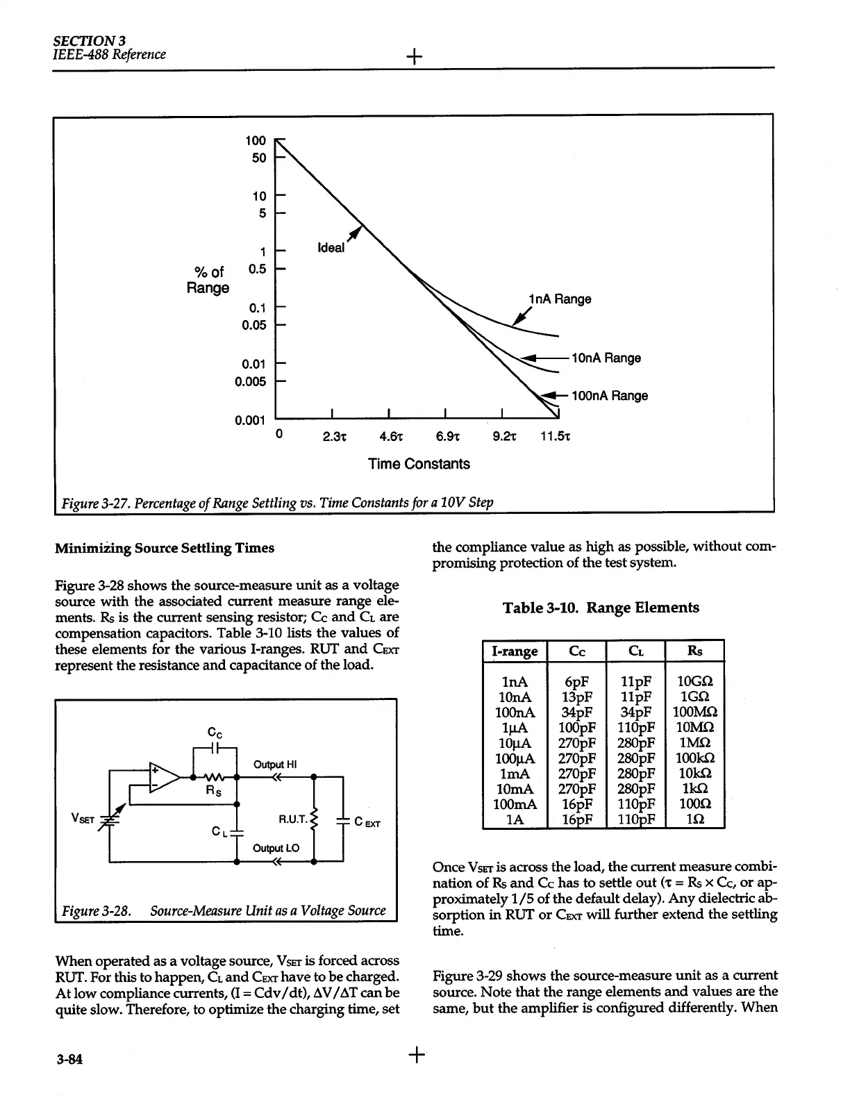
Figure
3-27.
Percentage
of
Range
Settling
vs.
Time
Constants
for
a
10V
Step
MinimiZing Source
Settling Times
Figure 3-28 shows the source-measure
unit
as a voltage
source with the associated current measure range ele-
ments.
Rs
is the current sensing resistor;
Cc
and
CL
are
compensation capacitors. Table 3-10
lists the
values of
these elements for the various !-ranges. RUT
and
CEXT
represent the resistance
and
capacitance of the load.
Output
HI
VsET
CEXT
Figure
3-28.
Source-Measure
Unit
as
a
Voltage
Source
When operated as a voltage source,
V
sET
is forced across
RUT.
For this to happen,
CL
and
CExr
have to
be
charged.
At
low compliance currents,
(I=
Cdv
I
dt),
fN
I
~T
can
be
quite slow. Therefore, to optimize the charging time, set
3-84
+
the compliance value as high as possible, without com-
promising protection of the test system.
Table
3-10.
Range Elements
1-range
Cc
CL
Rs
1nA
6pF
llpF
lOGO
10nA
13pF
llpF
1GQ
100nA
34pF
34pF
100MQ
1J.IA
100pF 110pF
10MQ
10J.IA
270pF
280pF
1MQ
100J.IA
270pF 280pF
1001<0
1mA
270pF
280pF
101<0
10mA 270pF
280pF
11<0
100mA
16pF
110pF
1000
1A 16pF
110pF
10
Once
VSET
is across the load, the current measure combi-
nation of
Rs
and
Cc
has to settle
out
(
't
=
Rs
x
Cc,
or
ap-
proximately
115
of the default delay).
Any
dielectric ab-
sorption in RUT
or
CEXT
will
further extend the settling
time.
Figure 3-29 shows the source-measure
unit
as a current
source. Note that the range elements
and
values are the
same,
but
the amplifier is configured differently. When
 Loading...


