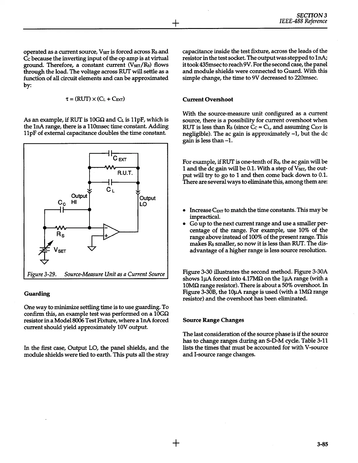
operated as a current source,
VsET
is forced across
Rs
and
Cc
because
the
inverting
input
of
the
op
amp
is
at
virtual
ground. Therefore, a constant current
(V
sET
/Rs)
flows
through the load. The voltage across RUT will settle as a
function
of
all circuit elements
and
can be approximated
by:
t
=
(RUT)
X
(CL
+
CEXT)
As
an
example,
if
RUT is
10Gn
and
CL
is 11pF, which is
the 1nA range, there is a
110msec
time constant.
Adding
11
pF
of external capacitance doubles the time constant.
Output
Cc
HI
Rs
VsET
CEXT
R.U.T.
Output
LO
Figure
3-29.
Source-Measure
Unit
as
a Current
Source
Guarding
One
way
to minimize settling time is to
use
guarding. To
confirm this,
an
example test
was
performed
on
a
10Gn
resistor
in
a
Model8006
Test Fixture,
where
a
1nA
forced
current should yield approximately 10V
output.
In
the
first case,
Output
LO,
the panel shields,
and
the
module shields
were
tied to earth. This
puts
all
the
stray
+
+
SECTION3
IEEE-488
Reference
capacitance inside the test fixture, across the leads of the
resistor
in
the test socket.
Theoutputwasstepped
to 1nA;
it
took 435msec to reach
9V.
For the second case, the panel
and
module
shields
were
connected to Guard. With
this
simple change,
the
time
to
9V decreased to 220msec.
Current
Overshoot
With the source-measure
unit
configured as a current
source, there is a possibility for current overshoot
when
RUT is less
than
Rs
(since Cc
=
CL,
and
assuming
CEXT
is
negligible). The ac gain is approximately
-1,
but
the de
gain is less
than
-1.
For example,
if
RUT is one-tenth
of
Rs,
the ac gain will be
1
and
the
de gain
will
be
0.1.
With a step
ofVsET,
the out-
put
will
try to go to 1
and
then
come back
down
to
0.1.
There are several
ways
to eliminate this,
among
them
are:
•
Increase
CEXT
to match
the
time constants. This
may
be
impractical.
•
Go
up
to
the
next current range
and
use
a smaller per-
centage
of
the
range. For example,
use
10%
of
the
range above instead
of
100%
of
the present range. This
makes
Rs
smaller,
so
now
it
is less
than
RUT. The dis-
advantage
of
a higher range is less source resolution.
Figure
3-30
illustrates
the
second method. Figure
3-30A
shows
1~
forced into
4.17Mn
on
the
1~
range (with a
10Mn
range resistor). There is
about
a
50%
overshoot.
In
Figure
3-30B,
the
10~
range is
used
(with a
1Mn
range
resistor)
and
the
overshoot has
been
eliminated.
Source
Range
Changes
The last consideration
of
the
source
phase
is
if
the source
has
to change ranges
during
an
5-D-M cycle. Table
3-11
lists
the
times
that
must
be
accounted for
with
V
-source
and
!-source range changes.
3-85
 Loading...


