+
APPENDIXF
236/237
Perfonnance
Verification
Interlock Cable (236-ILC-3)
( r
Waming: Connect
to
Safety
Earth
Ground
0
8006
Test
Fixture
A. Connections
6/237
23
(So
urce
V)
B. Schematic Equivalent
OUTPUTHI
~
OUTPUT~
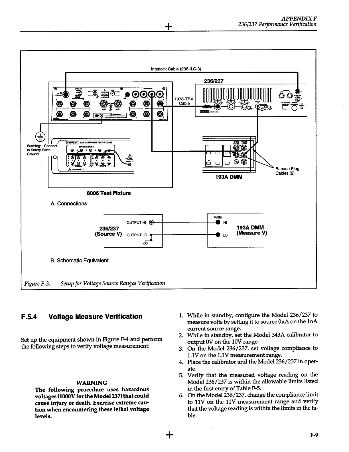
Figure
F-3.
Setup
for
Voltage
Source
Ranges
Verification
F.5.4
Voltage Measure Verification
Set
up
the equipment shown
in
Figure
F-4
and
perform
the following steps to verify voltage measurement:
WARNING
The
following procedure uses hazardous
voltages
(lOOOV
for
the
Model237)
that
could
cause
injury
or
death. Exercise extreme cau-
tion
when
encountering
these
lethal voltage
levels.
+
236/237
193ADMM
V!s
--HI
193ADMM
:
LO
(Measure V)
Banana
Plug
Cables
(2)
1.
While in standby, configure the
Model236/'237
to
measure volts
by
setting
it
to source
OnA
on the 1nA
current source range.
2.
While
in
standby, set the Model 343A calibrator to
output
OV
on
the
10V
range.
3.
On
the Model
236/'237,
set voltage compliance to
1.1
V
on
the
1.1
V
measurement range.
4.
Place the calibrator
and
the Model
'236/237
in oper-
·ate.
5.
Verify that the measured voltage reading
on
the
Model236/'237
is
within the allowable limits listed
in the first entry of Table
F-5.
6.
On
the
Model236/'237, change the compliance limit
to
11
V
on
the
11
V
measurement range
and
verify
that
the
voltage reading is within the limits in
theta-
ble.
F-9
 Loading...


