APPENDIXF
236/237
Performance
Verification
+
Interlock Cable (236-ILC-3)
Warning: Connect
to
Safety
Earth
Ground
8006
Test
Fixture
A. Connections
343
DC
Cal
(Sou
A
ibrator
rceV)
B.
Schematic
Equivalent
+-
OUTPUT
:
--
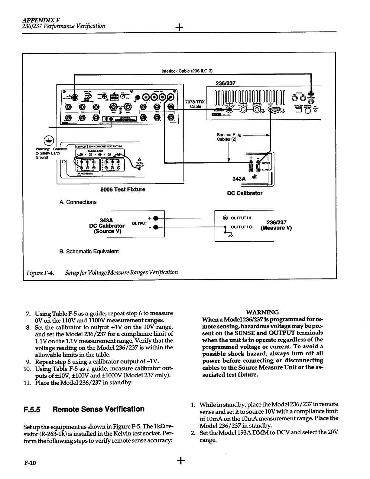
FigureF-4.
Setup
for
Voltage
Measure
Ranges
Verification
7.
Using Table
F-5
as a guide, repeat step 6 to measure
OV
on
the llOV
and
llOOV
measurement ranges.
8.
Set the calibrator to
output
+
1 V
on
the
lOV
range,
and
set the
Model236/'237
for a compliance limit of
1.1
Von
the
1.1
V measurement range. Verify that the
voltage reading
on
the Model236/'237
is within the
allowable limits
in
the table.
9.
Repeat step 8 using a calibrator
output
of -1V.
10.
Using Table
F-5
as a guide, measure calibrator out-
puts
of
±10V, ±100V
and
±1000V (Model
'237
only).
11.
Place the Model236
/'237
in
standby.
F.5.5
Remote
Sense
Verification
Set
up
the equipment as
shown
in
Figure F-5. The
lk.Q
re-
sistor (R-263-lk) is installed
in
the Kelvin test socket. Per-
form the following steps to verify remote sense accuracy:
F-10
+
236/237
Banana Plug
-----11._
Cables (2)
DC
Calibrator
~
OUTPUTHI
23
OUTPUTLO
6/237
sure
V)
(Mea
WARNING
When
a Model236/237
is
programmed
for
re-
mote
sensing,
hazardous
voltage
may
be
pre-
sent
on
the
SENSE
and
OUTPUT
terminals
when
the
unit
is
in
operate
regardless
of
the
programmed
voltage
or
current.
To
avoid
a
possible
shock
hazard,
always
turn
off
all
power
before
connecting
or
disconnecting
cables
to
the
Source
Measure
Unit
or
the
as-
sociated
test
fixture.
1.
While
in
standby, place the Model236/237
in
remote
sense
and
set
it
to source
10V
with
a compliance limit
of
lOrnA
on
the
lOrnA measurement range. Place the
Model236/237
in
standby.
2.
Set the Model193A DMM to DCV
and
select the
20V
range.
 Loading...


