APPENDIXF
236/237
Performance
Verification
+
Interlock Cable (236-ILC-3)
~'
~~
@)1
•®
.,
••
• •
®• •
8006
Test Fixture
A.
Connections
236/237
7078-TRX
Cables
(3)
Votts
Banana
Plug
Cables
(2)
2361237
(Source V)
OUTPUT HI
fel--1--....::=::=.:.~~
SENSE
HI
Cil--+--___/
Sense
HI
11<0
HI
193A
DMM
B.
Schematic
Equivalent
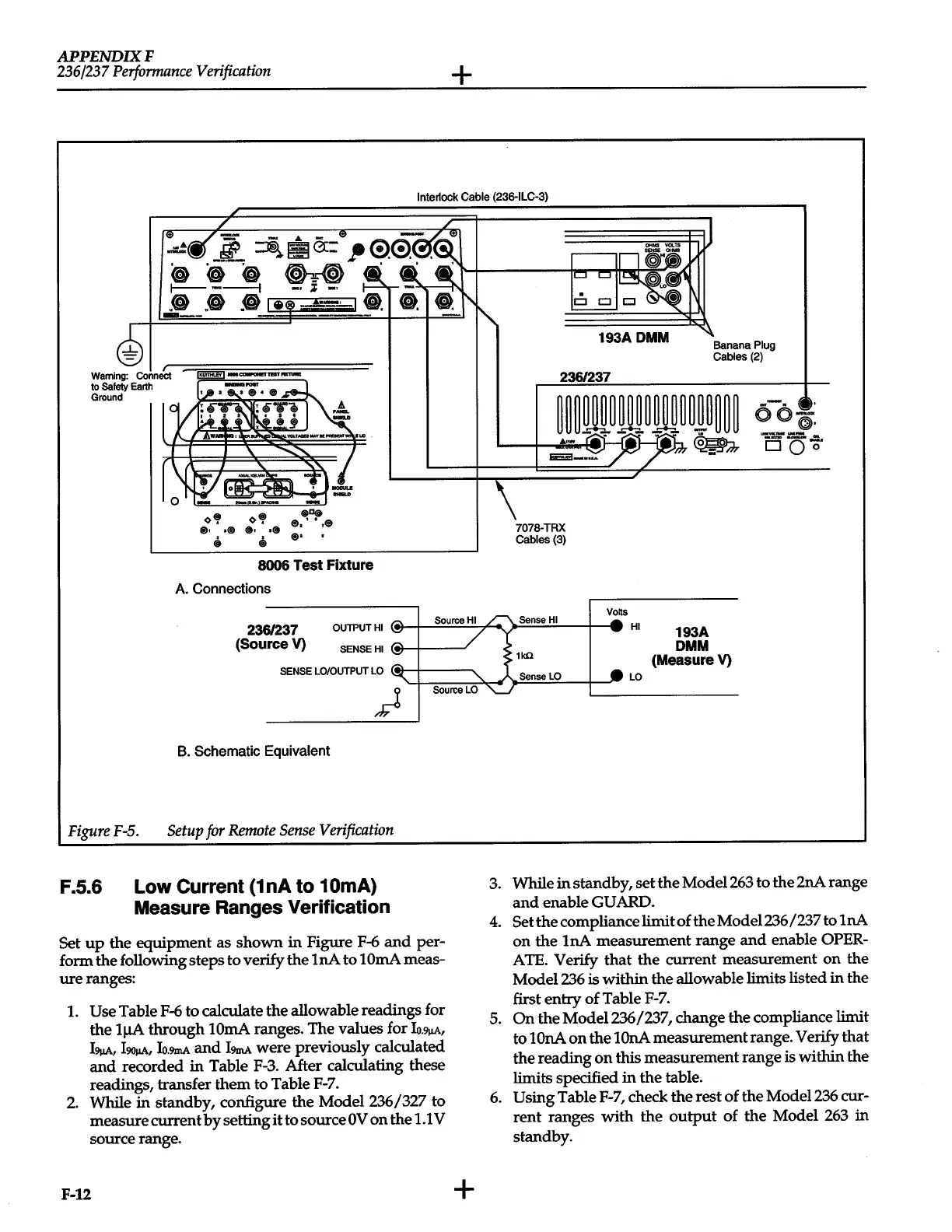
FigureF-5.
Setup
for
Remote
Sense
Verification
F.5.6
Low
Current
(1
nA
to
1
OmA)
Measure
Ranges
Verification
Set
up
the equipment as shown in Figure
F-6
and
per-
form the following steps to verify the
lnA
to
lOrnA
meas-
ure
ranges:
1.
Use
Table
F-6
to calculate the allowable readings for
the
lJ.IA
through
lOrnA
ranges. The values for
Io.9j1A,
l9!JA,
l90!1At
Io.9mA
and
l9mA
were previously calculated
and
recorded
in
Table
F-3.
After calculating these
readings, transfer them to Table
F-7.
2.
While in standby, configure the Model236/327 to
measure current
by
setting
it
to source
OV
on the
1.1
V
source range.
F-12
+
(MeasureV)
SenseLO
LO
3.
While
in
standby, set the Model263 to the 2nA range
and
enable
GUARD-
4.
Set
the compliance limit of the Model236 /237
tolnA
on the
lnA
measurement range
and
enable
OPER-
ATE.
Verify that the current measurement
on
the
Model236
is
within the allowable limits listed in the
first entry of Table
F-7.
5.
On
the Model236 /237, change the compliance limit
to
lOnA
on
the lOnA measurement range. Verify that
the reading
on
this
measurement range is within the
limits specified
in
the table.
6.
Using
Table
F-7,
check the rest of the Model236 cur-
rent ranges with the
output
of the Model
263
in
standby.
 Loading...


